Sharpening machine for sawteeth of saw band

A technology of grinding machine and saw belt, which is applied to tool dressing of sawing machine devices, metal sawing equipment, metal processing equipment, etc. and other problems, to achieve the effect of flexible and stable movement, good applicability and high precision of tool setting

Active Publication Date: 2010-09-15
TAIZHOU BEIPING MASCH TOOL CO LTD
View PDF6 Cites 11 Cited by
  • Summary
  • Abstract
  • Description
  • Claims
  • Application Information

AI Technical Summary

Problems solved by technology

The tool setting of the above-mentioned multifunctional saw grinder is to move the grinding wheel to the correct angle with the saw teeth by adjusting the position of the motor in the electric grinding wheel mechanism, but the motor is a small power motor and the supporting point of the motor is far away from the grinding wheel. For 35-15° saw band tool setting, a slight rotation of the motor will produce a large displacement in the lateral direction. For example, for saw bands with a large difference in the back angle of the saw tooth, a large-scale adjustment is required, and the tool setting and adjustment The process is cumbersome and basically difficult to achieve
Moreover, the tooth shifting and tooth grinding movements of the above mechanism are all completed by the saw band support part. Due to the long length of the saw band, the support on the workbench only accounts for 5% of the length of the saw band, and the upper end of the saw band is basically fixed. , Due to the inertia of forward and backward movement during grinding, the up and down movement of the saw band is not synchronized, and the saw band vibrates greatly during grinding, so it is obviously not suitable to complete the tooth grinding by the forward and backward movement of the saw band

Method used


Image

  • Sharpening machine for sawteeth of saw band
  • Sharpening machine for sawteeth of saw band
  • Sharpening machine for sawteeth of saw band

Examples


Embodiment Construction

[0032] The following are specific embodiments of the present invention and in conjunction with the accompanying drawings, the technical solutions of the present invention are further described, but the present invention is not limited to these embodiments.

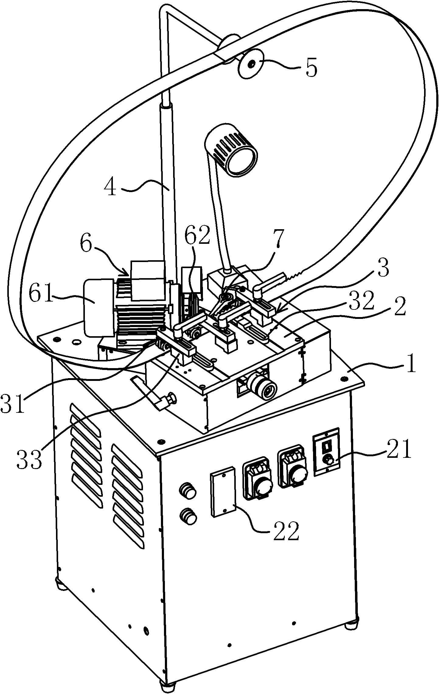
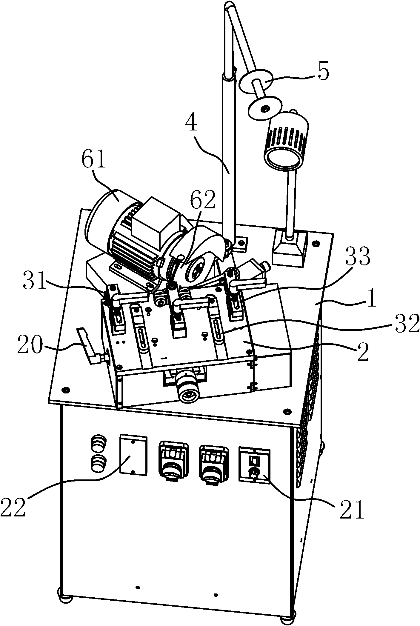
[0033] Such as figure 1 As shown, this saw band sawtooth grinding machine is composed of a workbench 1, a limit table 2, a limit mechanism 3, a grinding wheel motor assembly 6, a gear shifter 7, a power mechanism 8, a first transmission mechanism 10 and a second transmission mechanism 16 and other components.

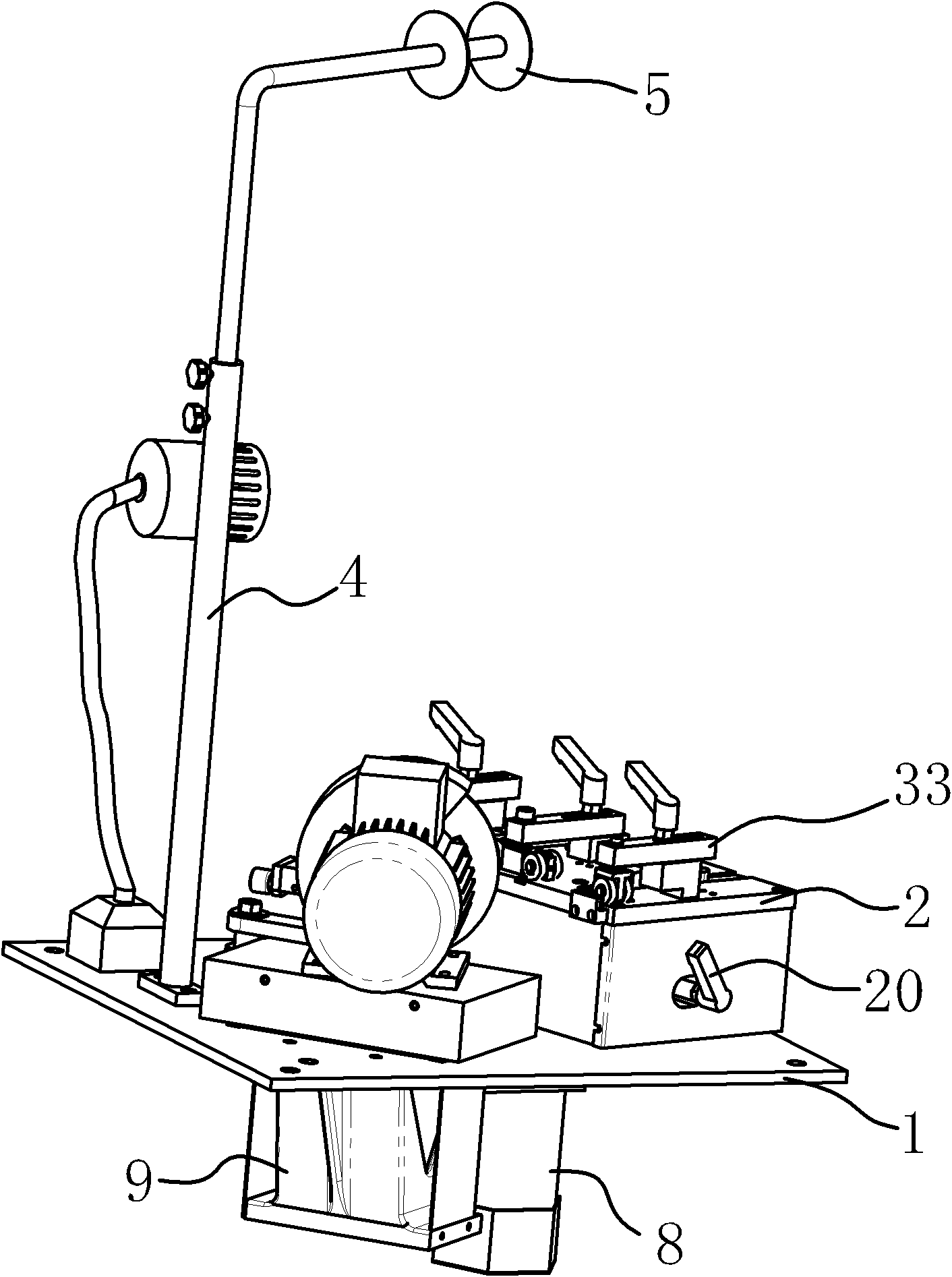
[0034] Such as figure 2 , image 3 As shown, a support rod 4 capable of supporting the saw band is fixedly connected to the workbench 1 , one end of the support rod 4 is fixedly connected to the workbench 1 , the other end is bent at a right angle and a roller 5 is connected to the end. The saw band is supported by the support rod 4, the saw band will not shake randomly during the grinding process, and the grind...


PUM


Abstract

The invention provides a sharpening machine for sawteeth of a saw band, belonging to the machine tool manufacturing technical field. The sharpening machine solves the problems of the existing sharpening machine tool for the sawteeth of the saw band such as inaccurate tool setting, small machining range and the like. The sharpening machine comprises a workbench, a limit mechanism, a grinding wheel drive motor assembly, a teeth shifting component and a power mechanism, wherein, the limit mechanism is arranged on the workbench for limiting the position of the saw band during a sharpening process; the end part of the teeth shifting component is embedded at the sawteeth of the saw band; the workbench is equipped with a spring steel plate; the grinding wheel drive motor assembly is arranged on the spring steel plate; a first transmission mechanism for driving the teeth shifting component to perform teeth shifting action is arranged between the power mechanism and the teeth shifting component, and a second transmission mechanism for driving the grinding wheel drive motor assembly to move in a straight line on the spring steel plate is arranged between the power mechanism and the grinding wheel drive motor assembly; and when the power mechanism works, the first transmission mechanism and the second transmission mechanism can drive the teeth shifting component and the grinding wheel drive motor assembly to make alternating movement. The sharpening machine has the advantages of high tool setting accuracy, good applicability, good stability and the like.

Description

technical field [0001] The invention belongs to the technical field of machine tool manufacturing, and relates to a band saw tooth grinding machine. Background technique [0002] At present, in the machinery industry, band saw machines are widely used in cutting metal materials. After the saw band used in the band saw machine is used for a period of time, the saw band is partially damaged, that is, a part of the saw teeth in the saw band will be worn or deformed. Continued use will cause the tip of the entire saw band to become blunt. In this way, the entire saw band cannot work normally, so the saw teeth of the saw band must be ground. In the past, the saw band was sharpened manually, but the efficiency was not high, and the quality of the sharpening also depended on the proficiency of the workers. [0003] In order to solve these problems that manual grinding saw bands produce, people have designed various machine tools for grinding saw band saw teeth, and some have also...

Claims


Application Information

Patent Timeline
Patent Type & Authority Applications(China)
IPC IPC(8): B23D63/12
Inventor 虞荣华
Owner TAIZHOU BEIPING MASCH TOOL CO LTD
Why Eureka
Try Eureka