Manual vacuum paint can and cup-free paint gun

A paint can and vacuum technology, applied in the field of paint cans, can solve problems such as environmental pollution, increased operator workload, and waste of water.

Inactive Publication Date: 2010-09-15
夏延德
View PDF5 Cites 4 Cited by
  • Summary
  • Abstract
  • Description
  • Claims
  • Application Information

AI Technical Summary

Problems solved by technology

This method of painting is time-consuming and labor-intensive
After the painting operation is completed, the spray cup must be cleaned with thinner, otherwise the spray cup can no longer be used, and thinner after use can often not be reused, resulting in waste of thinner, and the drained thi...

Method used


Image

  • Manual vacuum paint can and cup-free paint gun
  • Manual vacuum paint can and cup-free paint gun
  • Manual vacuum paint can and cup-free paint gun

Examples


Embodiment 1

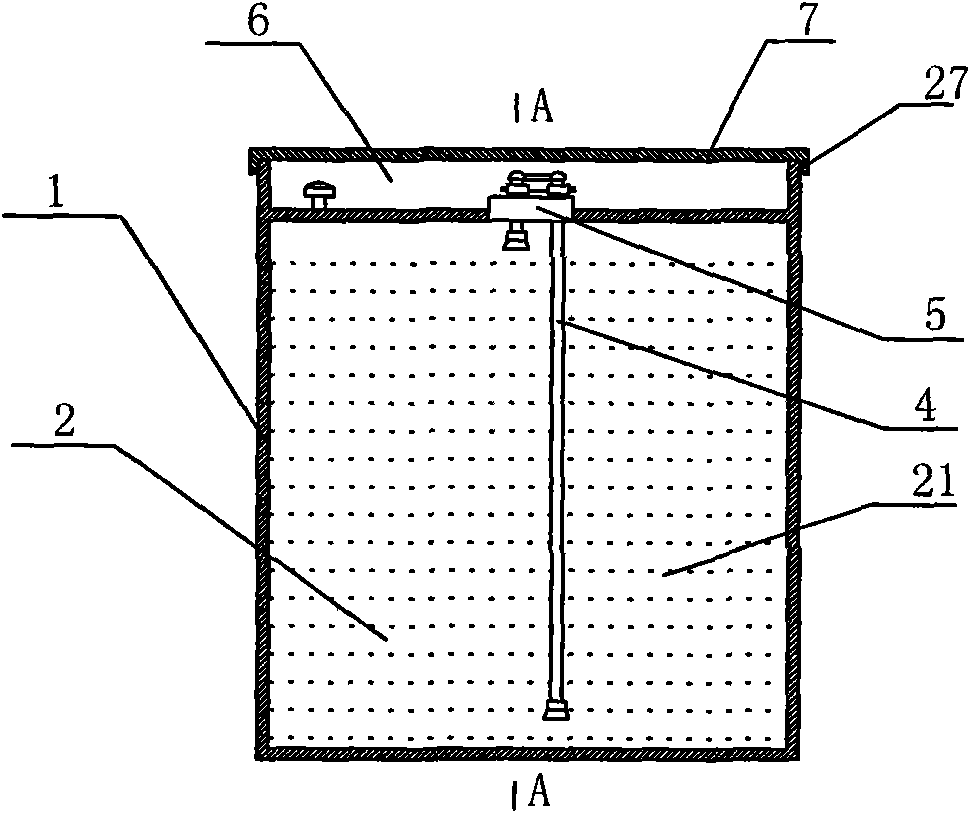
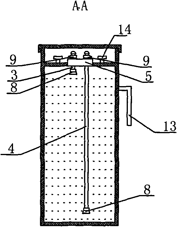
[0023] Such as Figure 1-Figure 3 As shown, the lower part of the tank body 1 of the manual vacuum paint tank has a paint storage chamber 2, and the paint storage chamber 2 is equipped with a paint 21. The upper part of the tank body 1 is a sealed chamber 6, and a top cover 7 is arranged above the sealed chamber 6, and the top cover 7 There is a sealing ring 27 between the tank body 1, which adopts snap-fit ​​connection or threaded connection. A return air connecting pipe 3 and a paint delivery connecting pipe 4 are installed above the paint storage chamber 2, the lower end of the return air connecting pipe 3 communicates with the upper space of the paint storage room 2, and the upper end of the return air connecting pipe 3 protrudes into the sealed chamber 6; the paint delivery connecting pipe 4 The lower end stretches to the bottom of the paint storage chamber 2, and the upper end stretches into the sealed chamber 6. The lower end of the air return connection pipe 3 and the...

Embodiment 2

[0025] Such as Figure 4-Figure 6 As shown, the lower part of the tank body 1 of the manual vacuum paint tank has a paint storage chamber 2, the upper part of the tank body 1 is a sealed chamber 6, and the top cover 7 above the sealed chamber 6 is connected to the tank body 1 as a whole, and the top cover 7 has The downward protruding part 12 has a threaded opening in the protruding part 12. There is a threaded cap 10 at the threaded port. There is a sealing gasket 11 between the threaded cap 10 and the threaded port. There is a handle 15 and a clamping post 14 above the threaded cap 10. Other With embodiment 1.

Embodiment 3

[0027] Such as Figure 7 As shown, the top of the tank body 1 of the manual vacuum paint tank has a sealed chamber 6, and the bottom has a paint storage chamber 2 and a curing agent chamber 23, and the curing agent chamber 23 is separated from the paint storage chamber 2. The top of the curing agent chamber 23 has a filling port, and a manual vacuum 5 is installed at the filling port. The top of the curing agent chamber 23 is provided with a second return air connecting pipe 26 and a curing agent connecting pipe 24. The lower end of the curing agent connecting pipe 24 extends to the bottom of the curing agent chamber 23. The curing agent connecting pipe 24 communicates with the paint conveying pipe 4. A mixer 25 is provided. The lower end of the second air return connecting pipe 26 communicates with the upper space of the curing agent chamber 23 , and the upper end communicates with the air return pipe 16 . A control valve 9 is arranged on the connecting pipe 24 for curing a...


PUM


Abstract

The invention discloses a manual vacuum paint can. A paint storage chamber and an airtight chamber are formed in a can body; a return gas connecting pipe, a paint conveying connecting pipe and a pouring port are arranged over the paint storage chamber; a manual vacuum is arranged at the pouring port; a cup-free paint gun is provided with a return gas pipe joint communicated with a high-pressure air inlet pipe and a paint conveying pipe joint communicated with a nozzle; a return gas pipe is connected with the return gas connecting pipe at the top of the paint storage chamber; and a paint conveying pipe is connected with the paint conveying connecting pipe. Paint spraying operation can be directly performed by connecting the paint conveying pipe and the paint conveying pipe joint of the cup-free paint gun and connecting the return gas pipe and the return gas pipe joint of the cup-free paint gun. Therefore, the paint gun does not need a spraying cup any more; the work of pouring paint into the spraying cup before paint spraying operation and washing the spraying cup after the paint spraying operation is eliminated; the working time can be saved; the labor intensity of operation workers is reduced; the working efficiency is improved; a thinner used for washing the spraying cup is saved; and pollution of the thinner which has washed the spraying cup to the environment is prevented.

Description

technical field [0001] The invention relates to a paint can, especially a manual vacuum paint can, and also relates to a cupless paint spray gun. Background technique [0002] Existing paint is usually filled in iron barrels or plastic barrels. When spraying paint, the operator needs to open the paint barrel or paint can, pour the paint into the spray cup, and then perform the painting operation. Sometimes, the paint and curing agent must be prepared in advance before being poured into the spray cup for painting. This kind of painting operation method is time-consuming and laborious. After the painting operation is completed, the spray cup must be cleaned with thinner, otherwise the spray cup can no longer be used, and thinner after use can often not be reused, resulting in waste of thinner, and the drained thinner is reused It will pollute the environment, and the work of cleaning the spray cups will also increase the workload of the operators. In addition, if the paint ...

Claims


Application Information

Patent Timeline
IPC IPC(8): B65D81/20B65D81/32B65D83/00B65D43/02B05B9/03
Inventor 夏延德
Owner 夏延德
Why Eureka
Try Eureka