
Efficient scroll compressor

A scroll compressor, high-efficiency technology, applied in the field of compressors to achieve the effects of low suction superheat, low cost, and reduced operating power

Active Publication Date: 2010-09-15
GUANGDONG GANEY PRECISION MACHINE CO LTD
View PDF6 Cites 0 Cited by
  • Summary
  • Abstract
  • Description
  • Claims
  • Application Information

AI Technical Summary

Problems solved by technology

[0006] The technical problem to be solved by the present invention is to provide a scroll compressor in view of the disadvantages of the prior art that the suction chamber of the scroll compressor is far away from the suction port of the compressor, causing suction throttling and suction overheating, and the overall structure of the compressor is bulky and cumbersome. Reasonable design of the suction chamber and exhaust port, light and practical overall structure, high-efficiency scroll compressor, eliminating the suction throttling and suction overheating caused by unreasonable structure, so as to overcome the deficiencies in the existing technology

Method used

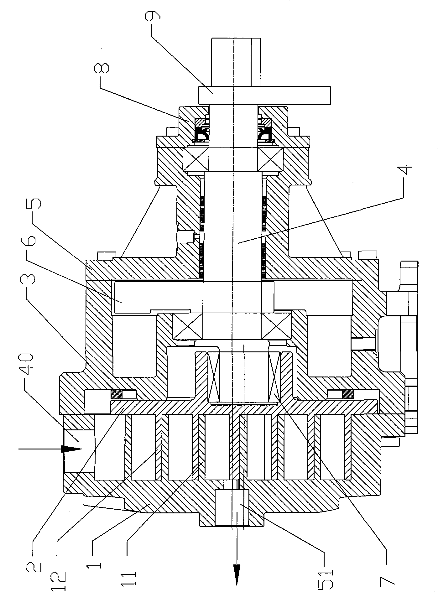

Image

  • Efficient scroll compressor
  • Efficient scroll compressor
  • Efficient scroll compressor

Examples


Embodiment Construction

[0017] The present invention will be further described below in conjunction with accompanying drawing.

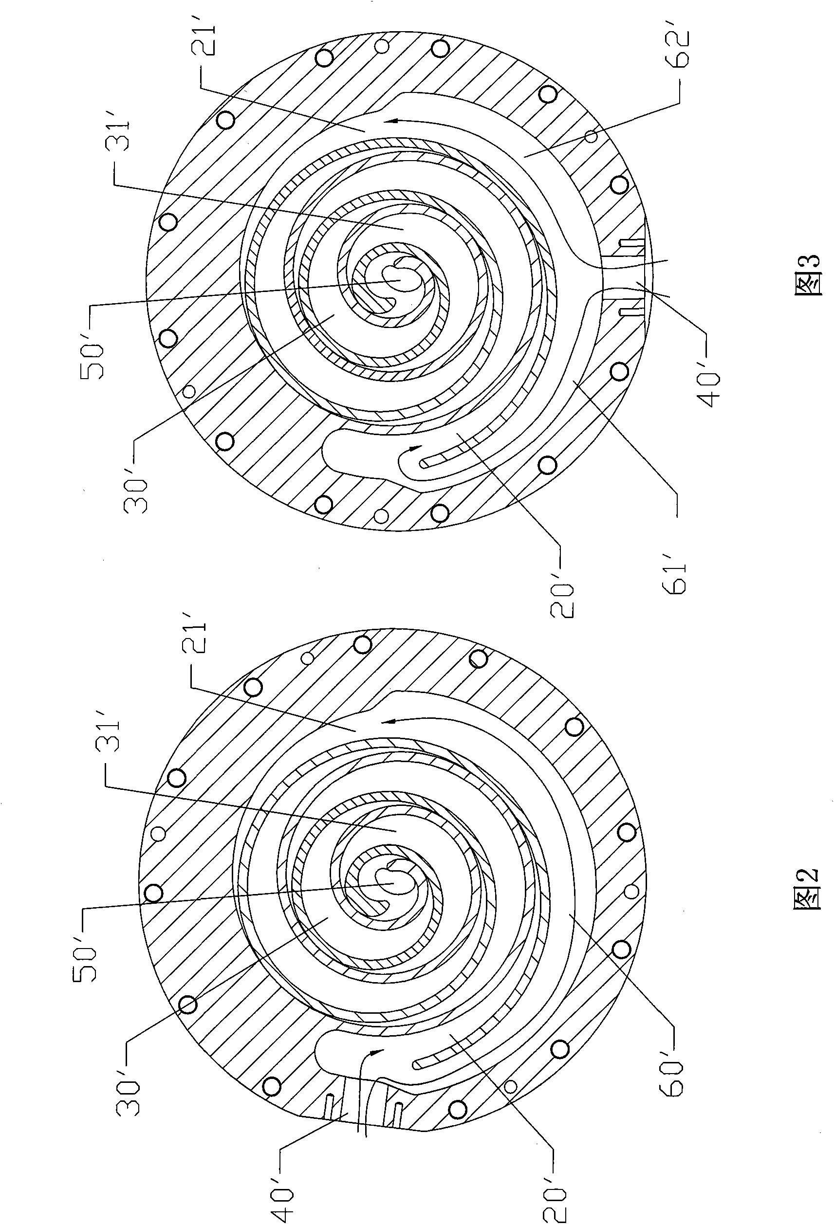
[0018] The engagement structure of the moving disk and the static disk of the scroll compressor in the prior art in the accompanying drawings is represented by symbols as follows:

[0019] Suction inner chamber 20' Suction outer chamber 21' Compression inner chamber 30'

[0020] Compression outer chamber 31' Suction port 40' Exhaust chamber 50'

[0021] Inspiratory flow channels 60', 61', 62'

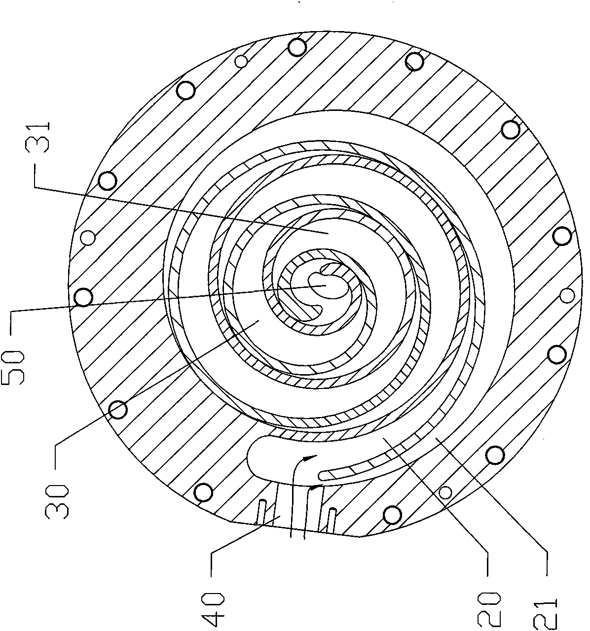
[0022] In the accompanying drawings, the components of the scroll compressor of the present invention are represented by labels as follows:

[0023] Static disk 1 Moving disk 2 Oldham ring 3 Crankshaft 4

[0024] Frame 5 main balance weight 6 bearing 7 rear cover 8

[0025] Auxiliary balance weight 9 Static disk scroll piece 11 Moving disk scroll piece 12

[0026] Suction inner chamber 20 Suction outer chamber 21 Compression inner chamber 30

[0027] Compression outer chamber 3...


PUM


Abstract

The invention discloses an efficient scroll compressor. The scroll compressor comprises a chassis, a stator disk, a rotor disk, a crank shaft, an intake port and an exhaust port, wherein the stator disk is fixed on the chassis through fasteners, the eccentric part of the crank shaft is inserted in the hub of the rotor disk, the crank shaft is arranged in the chassis through a main bearing and a supplementary bearing, the scroll molded lines of the stator disk and rotor disk are meshed mutually to form a suction inner cavity near the vortex center and a suction outer cavity far away the vortex center; and the stator disk is also provided with the intake port communicated with the suction inner cavity and the suction outer cavity and the exhaust port communicated with the exhaust port, the molded lines of the stator disk and rotor disk are not symmetrical, and the openings of the suction inner cavity and suction outer cavity are both near the intake port. As the suction inner and outer chambers are both near the intake port, the suction space is fully utilized, the sizes of the stator disk and rotor disk are minimized, the volume of the compressor is reduced and the cost of the product is lowered.

Description

technical field [0001] The present invention relates to the technical field of compressors, and more specifically relates to a method in which the static disk and the movable disk are engaged with each other, and the movable disk performs translational rotation, so that the cavity between the static disk and the movable disk gradually decreases toward the center, thereby achieving A high-efficiency scroll compressor for compression exhaust purposes. Background technique [0002] Scroll compressors are widely used in industrial, agricultural, transportation and other industries where compressed air is required due to their advantages of high efficiency, low noise, small size, and benefits for energy saving and environmental protection. The main moving part of the scroll compressor is the scroll, which is only meshed and does not produce wear. Therefore, the life is longer than that of the piston and screw compressors. It is an ideal power source for pneumatic machinery. In t...

Claims


Application Information

Patent Timeline
Patent Type & Authority Applications(China)
IPC IPC(8): F04C18/02F04C29/12F04C29/00
Inventor 李铃李华军魏建瑞
Owner GUANGDONG GANEY PRECISION MACHINE CO LTD
Learn More