Computer Aided Measurement Method of Steel Frame Beam-to-Column End-plate Joint Rotation Angle

A computer-aided measurement method technology, which is applied in the field of structural engineering steel structure, can solve the problem of inability to accurately measure the joint angle of beam-column end plate connection joints in steel frame structures, and achieve the effect of accurate measurement

Inactive Publication Date: 2012-02-08
TSINGHUA UNIV
View PDF0 Cites 0 Cited by
  • Summary
  • Abstract
  • Description
  • Claims
  • Application Information

AI Technical Summary

Problems solved by technology

[0003] In view of the problem that the existing research cannot accurately measure and calculate the joint angle of the beam-column end plate connection of the steel frame structure, the present invention proposes a variety of measurement and calculation methods, through the reasonable selection and arrangement of the measuring device, and calculates the joint angle according to the corresponding formula

Method used


Image

  • Computer Aided Measurement Method of Steel Frame Beam-to-Column End-plate Joint Rotation Angle
  • Computer Aided Measurement Method of Steel Frame Beam-to-Column End-plate Joint Rotation Angle
  • Computer Aided Measurement Method of Steel Frame Beam-to-Column End-plate Joint Rotation Angle

Examples


Embodiment 1

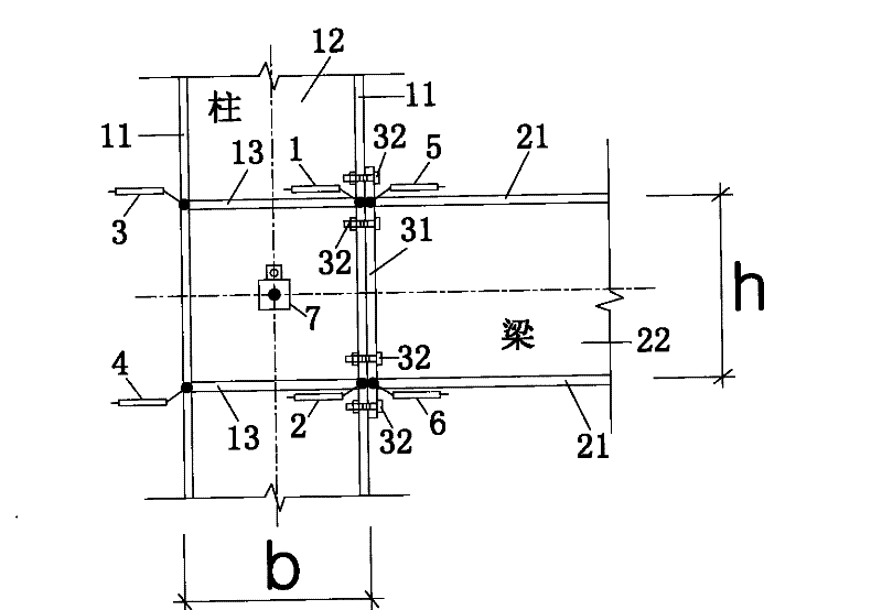
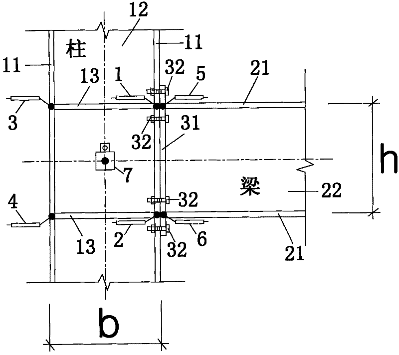
[0043] Embodiment 1 (see figure 1): This method is a method involving the measurement of the rotation angle of the end-plate joint in the experimental study of the mechanical performance of the steel frame joint, which is realized by 6 displacement meters and 1 inclinometer arranged at the end-plate joint. The column is composed of a column flange 11, a column web 12, and a horizontal stiffener 13 in the node domain. The beam is composed of a beam flange 21 and a beam web 22 . The end plate connection assembly consists of an end plate 32 and a high-strength friction bolt 32 . Displacement meter 1 measures the displacement of the corner point of the node domain adjacent to the tension flange of the beam along the axial direction of the beam, which is recorded as Δ 1 , the displacement meter 2 measures the displacement of the corner point of the node domain adjacent to the beam compression flange along the axial direction of the beam, which is recorded as Δ 2 , the displaceme...

Embodiment 2

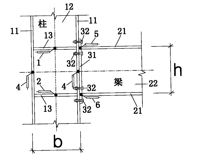
[0044] Embodiment 2 (see figure 2 ): This method is also a method involving the measurement of the rotation angle of the end-plate joints in the experimental study of the mechanical performance of the steel frame joints, which is realized by six displacement gauges arranged at the end-plate joints. The column is composed of a column flange 11, a column web 12, and a horizontal stiffener 13 in the node domain. The beam is composed of a beam flange 21 and a beam web 22 . The end plate connection assembly consists of an end plate 32 and a high-strength friction bolt 32 . Displacement meter 1 measures the displacement of the node domain along the axial direction of the beam at the intersection of the center line of the beam tension flange and the column axis, and the displacement is recorded as Δ 1 , the displacement meter 2 measures the displacement of the node domain along the beam axis at the intersection of the center line of the beam compression flange and the column axis,...


PUM


Abstract

The computer-aided measurement method of steel frame beam-column end-plate connection joint angle belongs to the experimental research field of steel frame structure beam-column joint mechanical performance. six displacement gauges at the points, at the corner points of the node domain opposite the flanges in tension or compression of the beam, at the ends of the flanges in tension or compression of the beam adjacent to the end plates, and mounting Measured by the inclinometer on the column web at the intersection of the beam and column axes, or by installing at the intersection of the centerline of the beam tension or compression flange and the column axis, or at the column flange adjacent to or opposite to the beam Six displacement gauges installed at the intersection of the center line and the beam axis, and at the end of the flange of the beam adjacent to the end plate under tension or compression, are measured and calculated. The invention has the advantages of high precision, effectively eliminating the influence of deformation of beams and columns, and being convenient and accurate when applied to steel frame structure design considering node deformation.

Description

technical field [0001] The invention relates to the technical field of structural engineering steel structures, in particular to the experimental research on the mechanical performance of the beam-column end-plate connection nodes of the steel frame structure and the design calculation of the steel frame structure. technical background [0002] Steel frame structures have been widely used at home and abroad, and the moment-rotation curves of beam-column joints have an important influence on the analysis and calculation of internal force and deformation of the frame and the design of beam-column components. Due to the differences in the research environment and research methods, most researchers at home and abroad use their own defined node rotation angles and measurement calculation methods, and the measurement results are inaccurate or incorrect, which makes a large number of research results obtained in terms of applicability and comparability. And there are bigger deficie...

Claims


Application Information

Patent Timeline
Patent Type & Authority Patents(China)
IPC IPC(8): G01B21/22G01B21/02
Inventor 施刚石永久王元清
Owner TSINGHUA UNIV
Why Eureka
Try Eureka