Supercharge Your Innovation With Domain-Expert AI Agents!

Camshaft position sensor

A sensor and camshaft technology, which is applied in the direction of transmitting sensing components by means of electric/magnetic devices, can solve the problems of high precision requirements, unfavorable production costs, and inability to be widely used.

Inactive Publication Date: 2010-09-15
UNITED AUTOMOTIVE ELECTRONICS SYST
View PDF3 Cites 0 Cited by
  • Summary
  • Abstract
  • Description
  • Claims
  • Application Information

AI Technical Summary

Problems solved by technology

[0006] At present, there is a method of packaging the chip and the magnetic circuit together through a special package, which requires high precision, which is not conducive to saving production costs and cannot be widely used.

Method used


Image

  • Camshaft position sensor
  • Camshaft position sensor
  • Camshaft position sensor

Examples


Embodiment 1

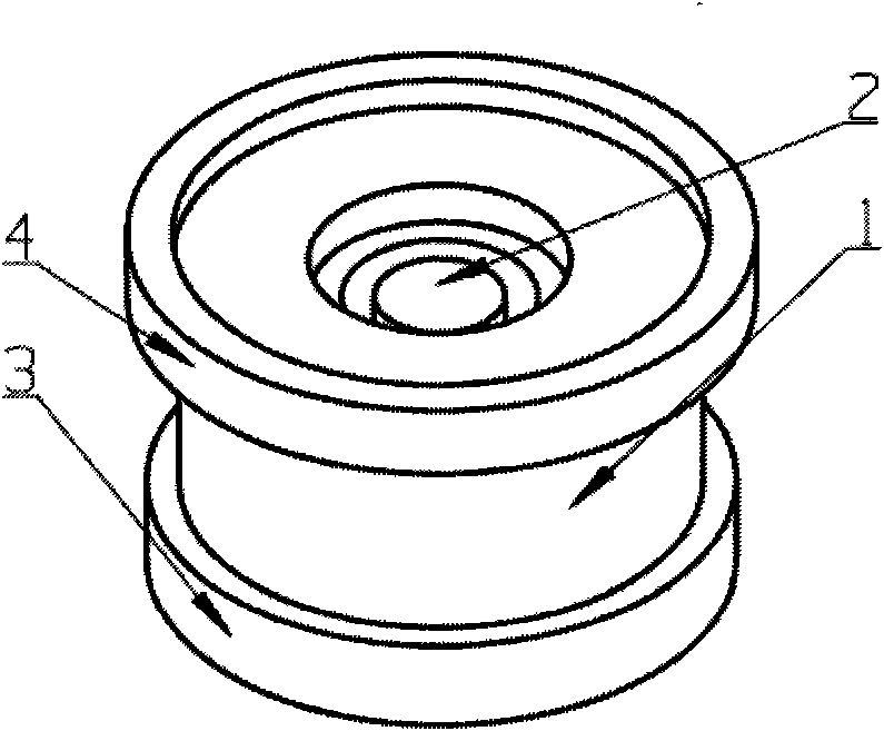
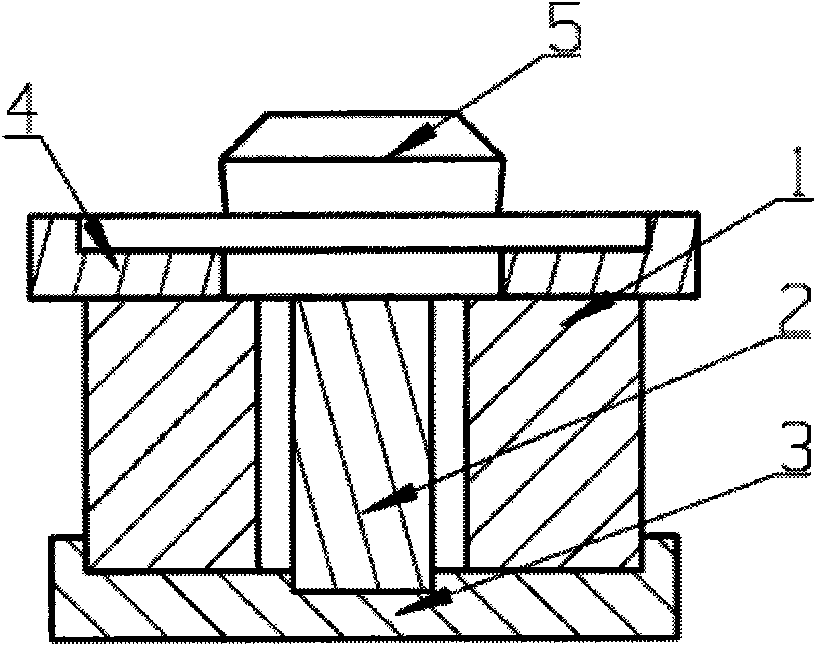
[0018] Such as figure 1 , figure 2 As shown, the camshaft position sensor includes an axially magnetized hollow magnet 1; a cylindrical soft iron 2 is installed inside the hollow magnet 1; a soft iron cover 4 is installed on one end face of the magnet, and a cylindrical soft iron 2 is connected The parts 3 are connected to form one; the magnet 1, the cylindrical soft iron 2 and the soft iron cover 4 form a magnetic circuit together; the magnetic flux sensing element 5 is installed on the end face of the soft iron cover 4, and the magnetic field strength there is measured and judged The location corresponding to this location. Such as figure 1 , figure 2 As shown, in this embodiment, the cylindrical soft iron 2 is a cylinder. Such as Figure 6 As shown, the soft iron cover on the surface of the magnet can make the change of the magnetic field near the measurement point small, and provide a larger range for the installation and positioning of the sensing element; at the s...

Embodiment 2

[0020] Such as image 3 As shown, the camshaft position sensor includes an axially magnetized hollow magnet 1; a cylindrical soft iron 2 is installed inside the hollow magnet 1; a soft iron cover 4 is installed on one end face of the magnet, and a cylindrical soft iron 2 is connected The parts 3 are connected to form one; the magnet 1, the cylindrical soft iron 2 and the soft iron cover 4 form a magnetic circuit together; the magnetic flux sensing element is installed on the end face of the soft iron cover 4, and the magnetic field strength at this place is measured and judged. corresponding location. Such as image 3 As shown, in this embodiment, the magnet is a column obtained by cutting off a plane from a cylinder, and there is a space for placing the soft iron in the column magnet.

Embodiment 3

[0022] Such as Figure 4 As shown, the camshaft position sensor includes an axially magnetized hollow magnet 1; a cylindrical soft iron 2 is installed inside the hollow magnet 1; a soft iron cover 4 is installed on one end face of the magnet, and a cylindrical soft iron 2 is connected The parts 3 are connected to form one; the magnet 1, the cylindrical soft iron 2 and the soft iron cover 4 form a magnetic circuit together; the magnetic flux sensing element is installed on the end face of the soft iron cover 4, and the magnetic field strength at this place is measured and judged. corresponding location. Such as Figure 4 As shown, in this embodiment, the magnet 1 , the cylindrical soft iron 2 , the non-magnetic conductive part 3 and the soft iron cover 4 can all be octagonal prisms.

[0023] Based on the idea of ​​the present invention, the magnet, soft iron, non-magnetic conductive parts and soft iron cover can also be cylinders of other shapes.


PUM


Abstract

The invention discloses a camshaft position sensor, which comprises a hollow magnet magnetizing axially; cylindrical soft iron is connected with a non-magnetic component into a whole; a soft iron cover is arranged on a magnet surface; the inner diameter of the hollow magnet is more than the diameter of the soft iron; the non-magnetic component is connected with the end face or outer cylindrical surface of the hollow magnet, so that the soft iron is positioned in the hollow magnet and forms a magnetic path with the soft iron cover; and a magnetic flux sensing element is arranged on the surface of the soft iron cover. The camshaft position sensor can generate a reasonable magnetic field, so that the field intensity of measuring points is suitable for corresponding sensing elements and the requirements on encapsulation accuracy of the sensor are reduced.

Description

technical field [0001] The invention relates to a vehicle sensor, in particular to a position sensor. Background technique [0002] At present, the inductive element of the camshaft sensor with the characteristic of getting the signal when it is powered on has very strict restrictions on the magnetic flux intensity. In the state where no ferromagnetic parts are close, the field intensity (Bwm) at this place needs to be less than a certain value. When the magnetic parts are close to each other, the field strength needs to be greater than a certain value, so a special magnetic circuit must be designed to meet this requirement. [0003] In U.S. Patent No. 5,814,985, an axially magnetized hollow magnet is used to have an opposite magnetic field on its surface. [0004] In U.S. Patent No. 6,278,269, adding soft iron inside the hollow magnet by means of interference fit or adding chemical binders weakens the field strength of the reverse magnetic field on its surface, making it m...

Claims


Application Information

Patent Timeline
IPC IPC(8): G01D5/12
Inventor 程捷王春健陈雁孙广建赵奇巍
Owner UNITED AUTOMOTIVE ELECTRONICS SYST
Features
  • R&D
  • Intellectual Property
  • Life Sciences
  • Materials
  • Tech Scout
  • Unparalleled Data Quality
  • Higher Quality Content
  • 60% Fewer Hallucinations
Learn More