
Controllable dynamic shape interpolation method with physical third dimension

A dynamic shape and interpolation method technology, applied in image data processing, 3D image processing, instruments, etc., can solve the problems of low physical reality of interpolation results, high computational complexity, and high computational cost, so as to enhance the physical reality. , the effect of enhancing visual effects and improving computational efficiency

Inactive Publication Date: 2010-09-15
ZHEJIANG UNIV
View PDF3 Cites 17 Cited by
  • Summary
  • Abstract
  • Description
  • Claims
  • Application Information

AI Technical Summary

Problems solved by technology

One of the widely used techniques is to keep the details of the surface as much as possible during the deformation process. First, the local transformation of each vertex or patch is interpolated, and then the least squares technique can be used to obtain the Local interpolation transformation best fits the deformation trajectory. The interpolation results of these methods do not have a strong sense of physical reality and do not have much controllability.
In addition, there is also a method to optimize the geodesic path between two models under a certain geometric measure (such as maintaining the model volume, etc.) in the shape space defined by the model. This method is computationally expensive and not suitable for real-time interaction. application
Another type of method is a physics-based method. After the relevant physical properties of the object model are given, for an elastic body, an optimal position between two postures can be obtained theoretically through time-space constraints or optimal control methods. The deformation process, but the method based on physical properties often has a large amount of calculation, especially after some physical properties or related constraints are modified, it often needs to be calculated with high complexity, and real-time interactive editing and modification cannot be performed.

Method used


Image

  • Controllable dynamic shape interpolation method with physical third dimension
  • Controllable dynamic shape interpolation method with physical third dimension
  • Controllable dynamic shape interpolation method with physical third dimension

Examples


Embodiment

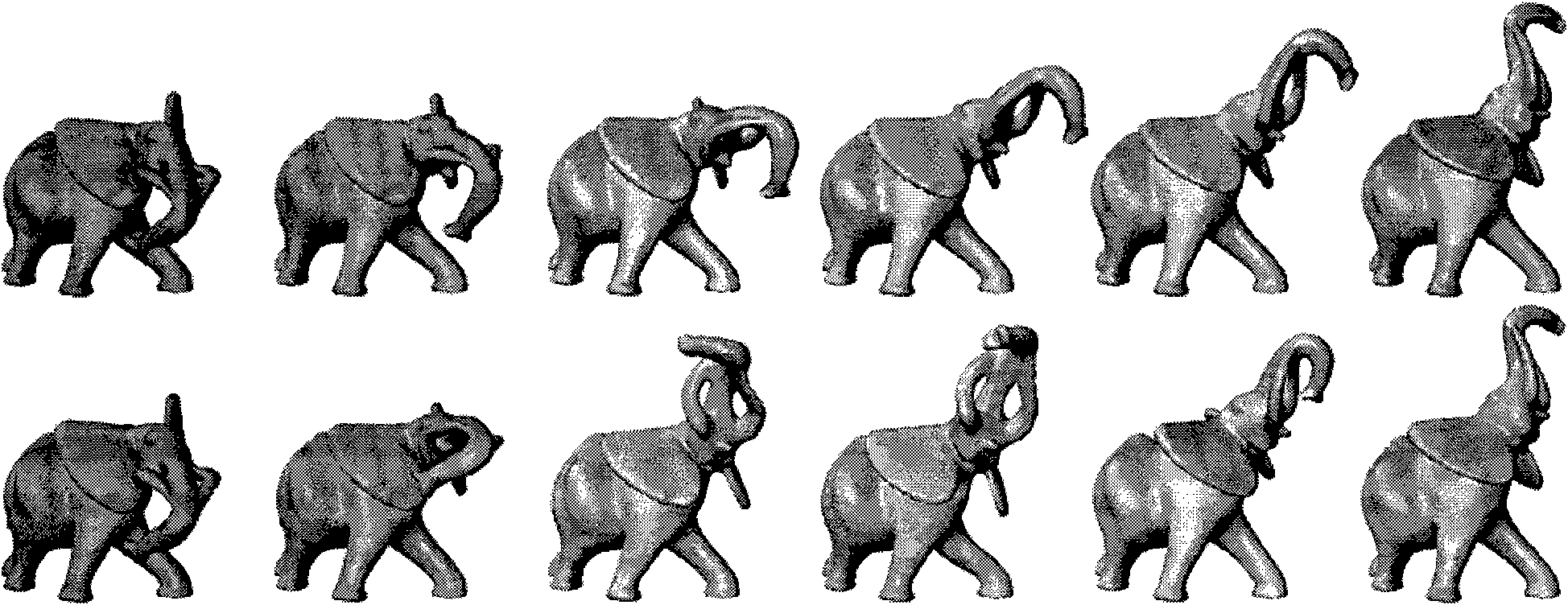
[0071] image 3 and Image 6 It can be regarded as a specific implementation example of the method.

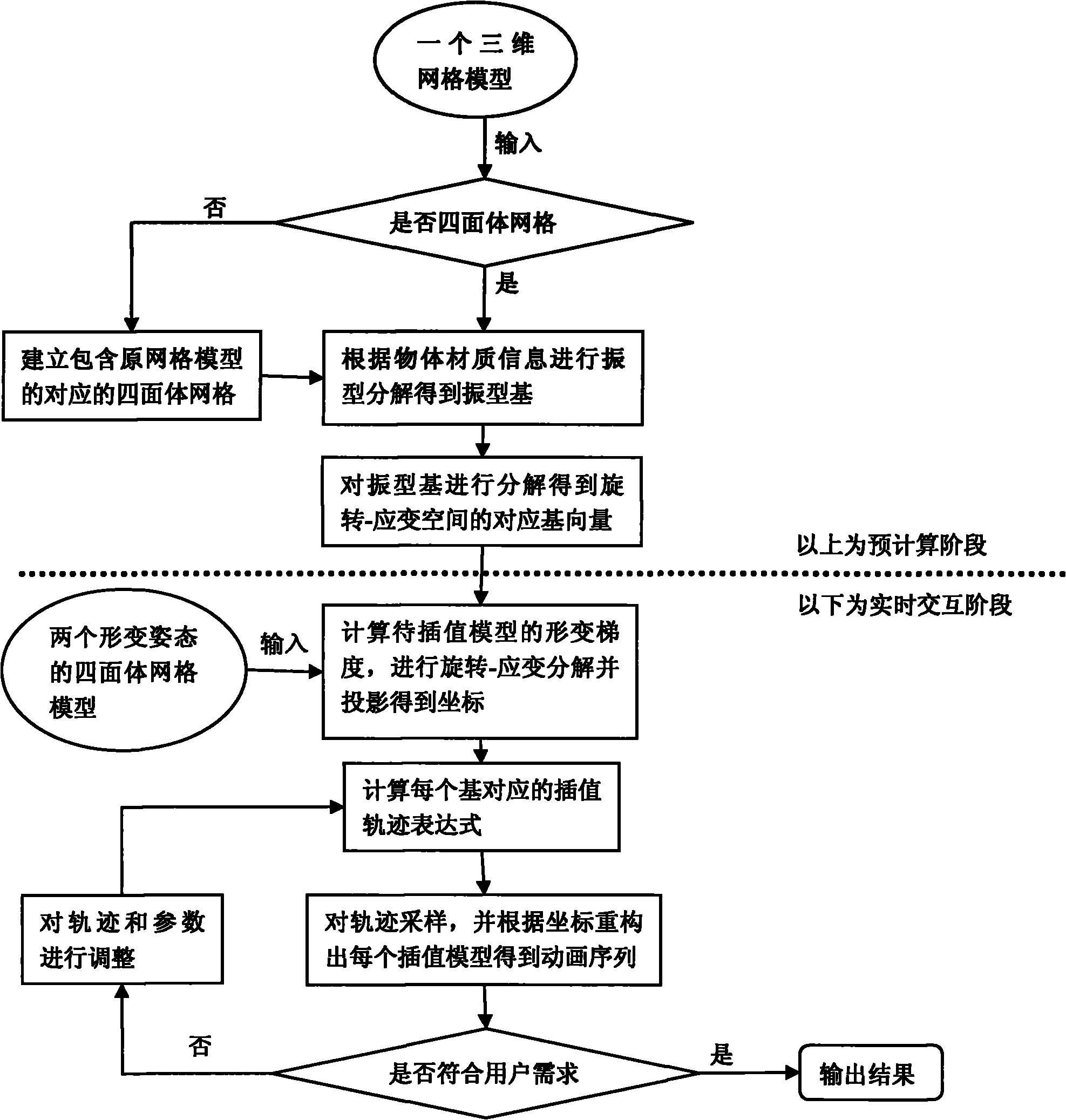
[0072] exist image 3In the example shown, the given two keyframe models to be interpolated are the first and sixth models in the first row (the keyframe models in the second row are the same), and the goal is to generate these two frame models transition animation between. In the first step, the two models are three-dimensional triangular meshes. First, corresponding tetrahedral models that can contain the two models are generated. The topological connections of the two tetrahedral models are the same, but the positions of the vertices are different. In the second step, the first frame model is regarded as a static model. According to the material information of the model, the mass matrix and stiffness matrix of the object are constructed and the mode shape decomposition is performed to obtain a set of basis vectors corresponding to the traditional mode shape decomposition...


PUM


Abstract

The invention discloses a controllable dynamic shape interpolation method with physical third dimension. According to the method, a rotation-strain space definition is provided, and a set of conversion mode from a three-dimensional model to a rotation-strain space coordinate is established, so that the primary nonlinear deformation can be expressed by linear operation of the coordinate in the rotation-strain space; and the method greatly reduces the algorithm complexity and improves the solving efficiency by combining the traditional mode shape decomposition to perform dimension reduction. The method comprises the following steps of: decomposing a base vector acquired by the traditional mode shape decomposition into rotation and strain parts, and constructing a deformation subspace by using rotation-strain corresponding to the main component bases; obtaining a rich dynamic deformation effect by editing and regulating mode shape coordinate motion interpolation curve parameters in the subspace; and finally, obtaining a new model pose sequence through a reconstruction process according to the interpolated mode shape coordinate.

Description

technical field [0001] The invention relates to a computer transition animation generation technology based on three-dimensional model shape interpolation in the animation production industry, in particular to an interactively controllable shape interpolation method with a sense of physical reality and dynamic effects. technical background [0002] The present invention is aimed at a very basic and important technical problem in the animation production industry. Generally speaking, the animation key frame model created by an animator (that is, the user mentioned in this article) is very limited, and most of the animation time is filled by the transition animation generated according to the key frame. Transition animation generation technology greatly determines the efficiency and effect of animation production. [0003] The shape interpolation problem of a 3D model can be described as: Given two topologically consistent 3D models as the shapes at time t=0 and time t=1 resp...

Claims


Application Information

Patent Timeline
IPC IPC(8): G06T15/70
Inventor 黄劲鲍虎军
Owner ZHEJIANG UNIV
Learn More