Constant velocity universal joint

A constant velocity universal joint and outer joint technology, applied in elastic couplings, mechanical equipment, couplings, etc., can solve the problem that it is difficult to ensure the strength of the inner ring 120, and achieve the effect of long-life reliability

Active Publication Date: 2010-09-15
NTN CORP
View PDF4 Cites 1 Cited by
  • Summary
  • Abstract
  • Description
  • Claims
  • Application Information

AI Technical Summary

Problems solved by technology

[0015] As a result, when the fixed constant velocity universal joint takes a high action angle, the inlet-side end surface 123 of the inner ring 120 is at the bottom of the raceway groove 124, and the stress from the balls located in the raceway groove 124 , so it becomes the weakest part, making it difficult to ensure sufficient strength of the inner ring 120

Method used


Image

  • Constant velocity universal joint
  • Constant velocity universal joint
  • Constant velocity universal joint

Examples


Embodiment Construction

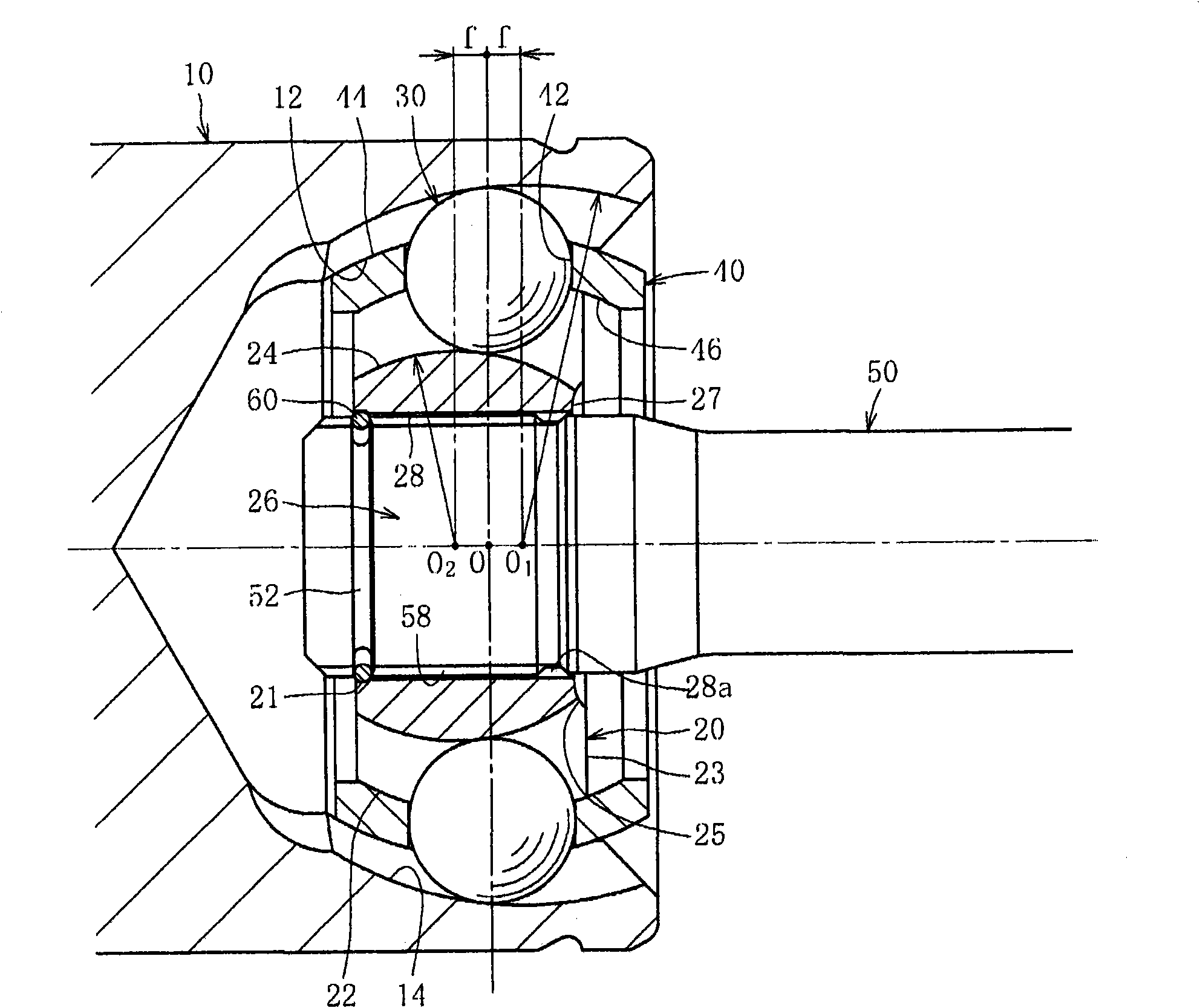
[0033] Embodiments of the constant velocity universal joint of the present invention will be described in detail. figure 1 The illustrated embodiment illustrates a Burfield-type fixed constant velocity universal joint (BJ) having an outer joint part and an inner joint part with raceway grooves that The longitudinal section in the axial direction of the raceway has a single arc shape.

[0034] In addition, although not shown, it can also be applied to an undercut type fixed constant velocity universal joint (UJ) having an outer joint member and an inner joint member having track grooves, The track groove has a straight portion parallel to the axial direction. In addition, it is also applicable to other fixed type constant velocity universal joints having track groove shapes other than these Burfield type or undercut type.

[0035] figure 1The shown BJ-type fixed constant velocity universal joint has: an outer ring 10, which is an outer joint component and is formed with a ...


PUM


Abstract

A constant velocity universal joint in which, despite an inner ring having a reduced wall thickness for weight reduction and size reduction, the inner ring has sufficient strength even in operation at a large operation angle and under high torque loading. The constant velocity universal joint has an outer ring (10) having, formed in its inner peripheral surface (12), axially extending track grooves (14); the inner ring (20) having, formed in its outer peripheral surface (22), axially extending track grooves (24)extending while being paired with the track grooves (14) of the outer ring (10) and also having a shaft hole (26) that has, formed in its inner peripheral surface, axially extending splines (28); balls (30) arranged between the track grooves (14) of the outer ring (10) and the track grooves (24) of the inner ring (20) and transmitting torque; and a cage (40) placed between the inner peripheral surface (12) of the outer ring (10) and the outer peripheral surface (22) of the inner ring (20) and retaining the balls (30). An axial step (25) is formed between an entrance-side end surface (23) of the inner ring (20) and a spline end section (28a) of the shaft hole (26), and a recessed end surface (27) is formed on the inward side of the entrance-side end surface (23).

Description

technical field [0001] The present invention relates to a constant velocity universal joint, which is used, for example, in a power transmission system of an automobile or various industrial machines, and which allows only an operating angular displacement between two shafts on a driving side and a driven side. Background technique [0002] For example, there is a fixed type constant velocity universal joint used as means for transmitting rotational force from an engine of an automobile to wheels at a constant velocity. This fixed type constant velocity universal joint has a structure that can transmit rotational torque at a constant velocity even if two shafts on the driving side and the driven side are connected and the two shafts take an operating angle. Generally, as the fixed type constant velocity universal joint, a Birfield type (BJ) or an undercut free type (UJ) is widely known. [0003] For example, a BJ-type fixed constant velocity universal joint has an outer rin...

Claims


Application Information

Patent Timeline
Patent Type & Authority Applications(China)
IPC IPC(8): F16D3/224F16D3/20F16D3/223F16D3/2237
CPCF16D3/2245F16D2003/22313
Inventor 小林正纯
Owner NTN CORP
Why Eureka
Try Eureka