Non-skid tire
A technology of anti-skid tires and anti-skid teeth, which is applied to tire parts, tire tread/tread pattern, transportation and packaging, etc. It can solve the problems of reduced grounding performance, limited grounding area, and easy to fall blocks, etc., to improve tire grip The effect of focusing force, increasing the ground contact area, and increasing friction
- Summary
- Abstract
- Description
- Claims
- Application Information
AI Technical Summary
Problems solved by technology
Method used
Image
Examples
Embodiment 1
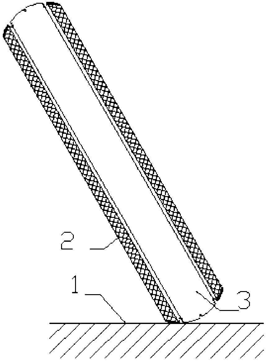
[0043] Combined with the accompanying drawings, figure 1 is a schematic diagram of the tire turning ground state, Figure 7 It is the force analysis diagram when the tire turns and touches the ground. When the two-wheeled vehicle is turning, the wheels are tilted due to centrifugal force, and the contact point with the ground is no longer the tire crown, but the joint between the tire crown and the sidewall. At the same time, the force on the wheel changes, and the contact point of the wheel tire is affected by four directions of force, namely, the gravity f2 of the driver and the vehicle, the ground support force f1, the ground friction force f4, and the centrifugal force f3. If the friction between the tire and the ground is too small, it will skid and roll over. At this time, the ground friction force f4 is generated by the joint between the crown and the sidewall and the ground.
[0044] There are two main solutions to improve tire grip and increase friction. One is to ...
Embodiment 2
[0050] The grooves on the surface of the tire can increase the friction between the tire and the ground and can better drain water in rainy days. On rainy days or muddy roads, due to the action of rainwater and muddy water, the friction force decreases after the tire surface adheres to rainwater and muddy water. The grooves on the tire surface can collect water and mud well, reduce adhesion and increase friction force.
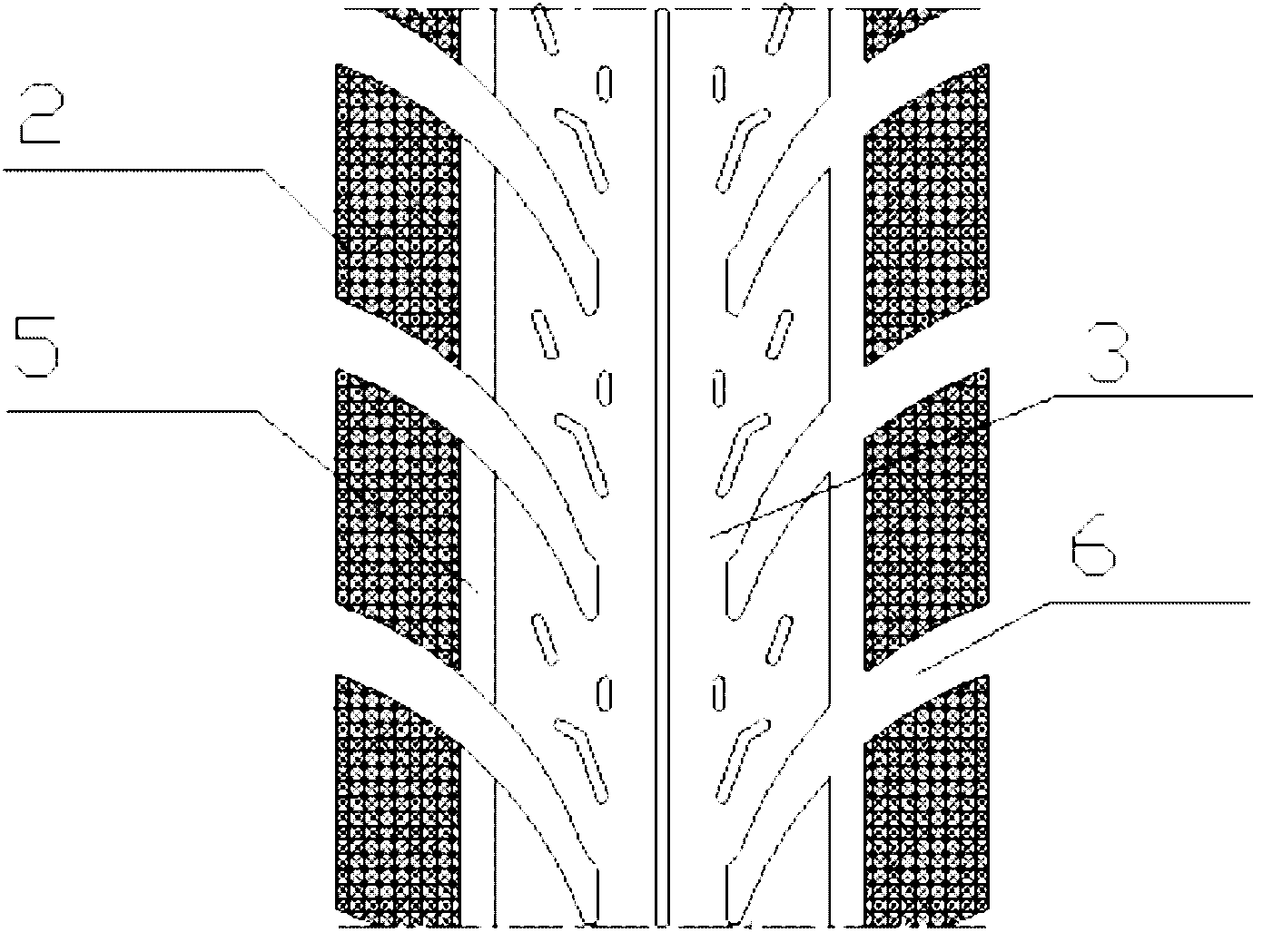
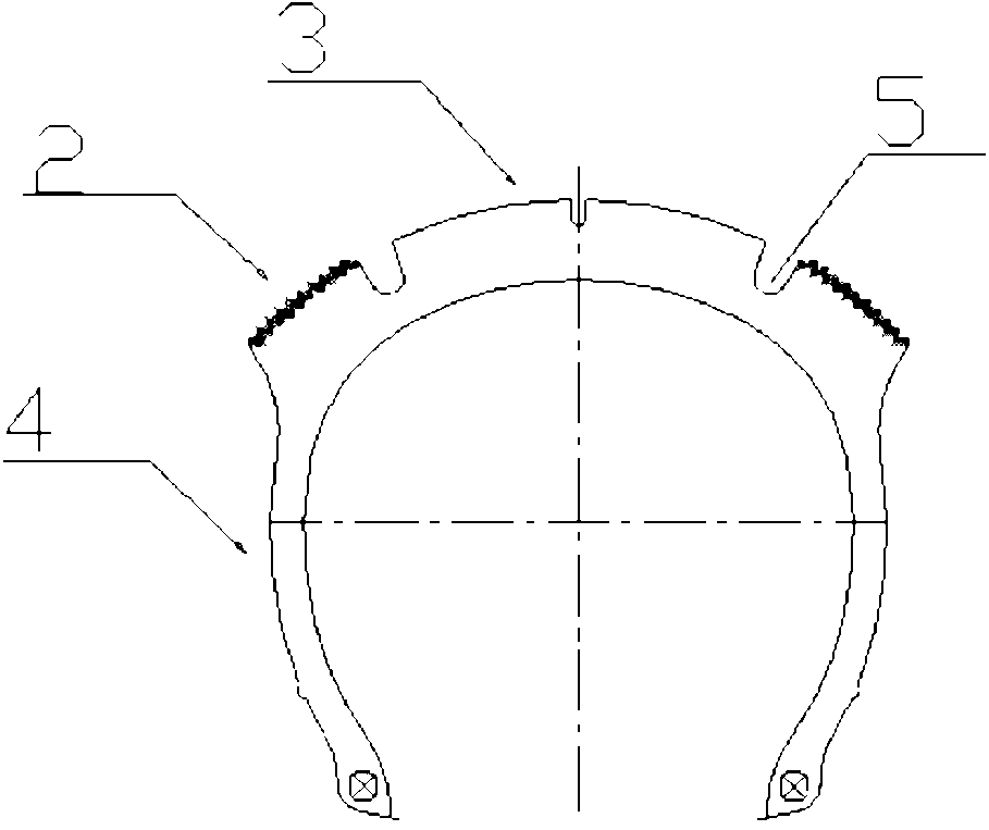
[0051] to combine figure 1 , figure 2 , image 3 . figure 2 It is a schematic diagram of the surface structure of the tire in this embodiment, image 3 It is a schematic diagram of the cross-sectional structure of the tire of this embodiment. In this example, there is a concave groove 5 between the tire shoulder formed by the anti-skid teeth and the tire crown, and the depth is 5 mm to 12 mm. The other structures are the same as in embodiment 1. The groove 5 surrounds the tire, between the tire shoulder formed by the anti-skid teeth and the tire crown, ...
Embodiment 3
[0053] to combine figure 1 , figure 2 . In this embodiment, there is a groove 6 in the anti-skid shoulder of the tire, and other structures are the same as in Embodiment 1 or Embodiment 2.
[0054] The dimples 6 are evenly distributed in the tire shoulder 2, the size and number of which are determined according to the practicality of the tire, and the depth is generally 5 mm to 12 mm. The concave grooves 6 have a similar effect to the concave grooves 5, and the concave grooves 6 are nearly laterally distributed in the tire shoulder 2, and can further increase the forward frictional force.
PUM
| Property | Measurement | Unit |
|---|---|---|
| Depth | aaaaa | aaaaa |
| Bottom width | aaaaa | aaaaa |
| Height | aaaaa | aaaaa |
Abstract
Description
Claims
Application Information
 - R&D
- Intellectual Property
- Life Sciences
- Materials
- Tech Scout
- Unparalleled Data Quality
- Higher Quality Content
- 60% Fewer Hallucinations
Browse by: Latest US Patents, China's latest patents, Technical Efficacy Thesaurus, Application Domain, Technology Topic, Popular Technical Reports.
© 2025 PatSnap. All rights reserved.Legal|Privacy policy|Modern Slavery Act Transparency Statement|Sitemap|About US| Contact US: help@patsnap.com


