Energy-dissipating element and impact protection with an energy-dissipating element

A technology of energy dissipation and shock absorber, which is applied in the direction of elastic shock absorber, transportation and packaging, buffer, etc., can solve the problem of no transmission support structure for impact force, achieve low longitudinal shortening, and reduce the required space Effect

Inactive Publication Date: 2010-09-22
VOITH PATENT GMBH
View PDF1 Cites 5 Cited by
  • Summary
  • Abstract
  • Description
  • Claims
  • Application Information

AI Technical Summary

Problems solved by technology

[0007] The printed publication DE 102 52 175 A1 takes into account the following problem: After the maximum damper stroke has been reached, i.e. after the damping properties of the damping element have been exhausted, impact forces exceeding the characteristic operating load of the piston damper are not further undamped conduction to the supporting structure
[0010] The disadvantage of this technique is that, based on its design, this prior art solution can only use about half of the entire length of the buffer when absorbing shocks

Method used


Image

  • Energy-dissipating element and impact protection with an energy-dissipating element
  • Energy-dissipating element and impact protection with an energy-dissipating element
  • Energy-dissipating element and impact protection with an energy-dissipating element

Examples


Embodiment Construction

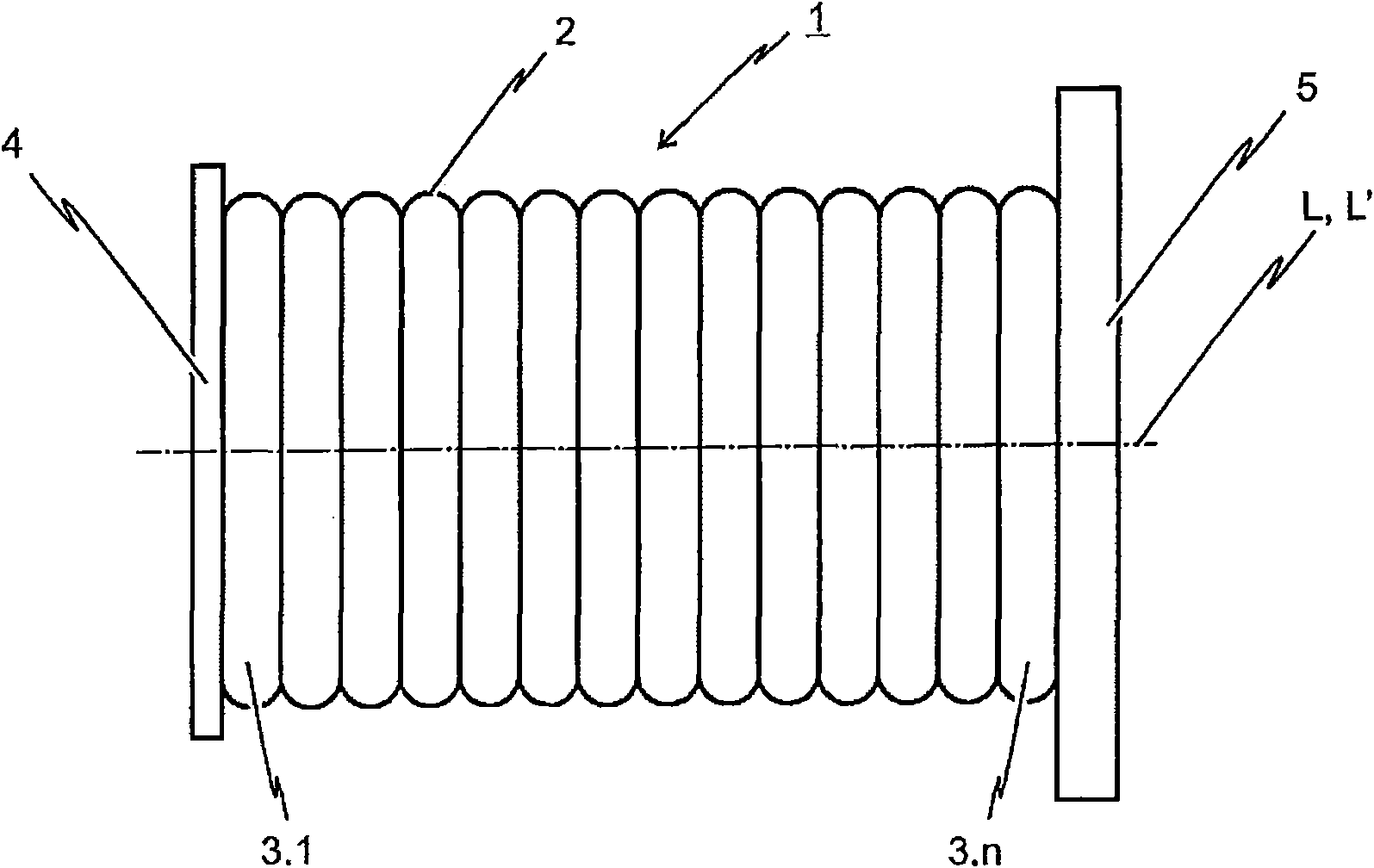
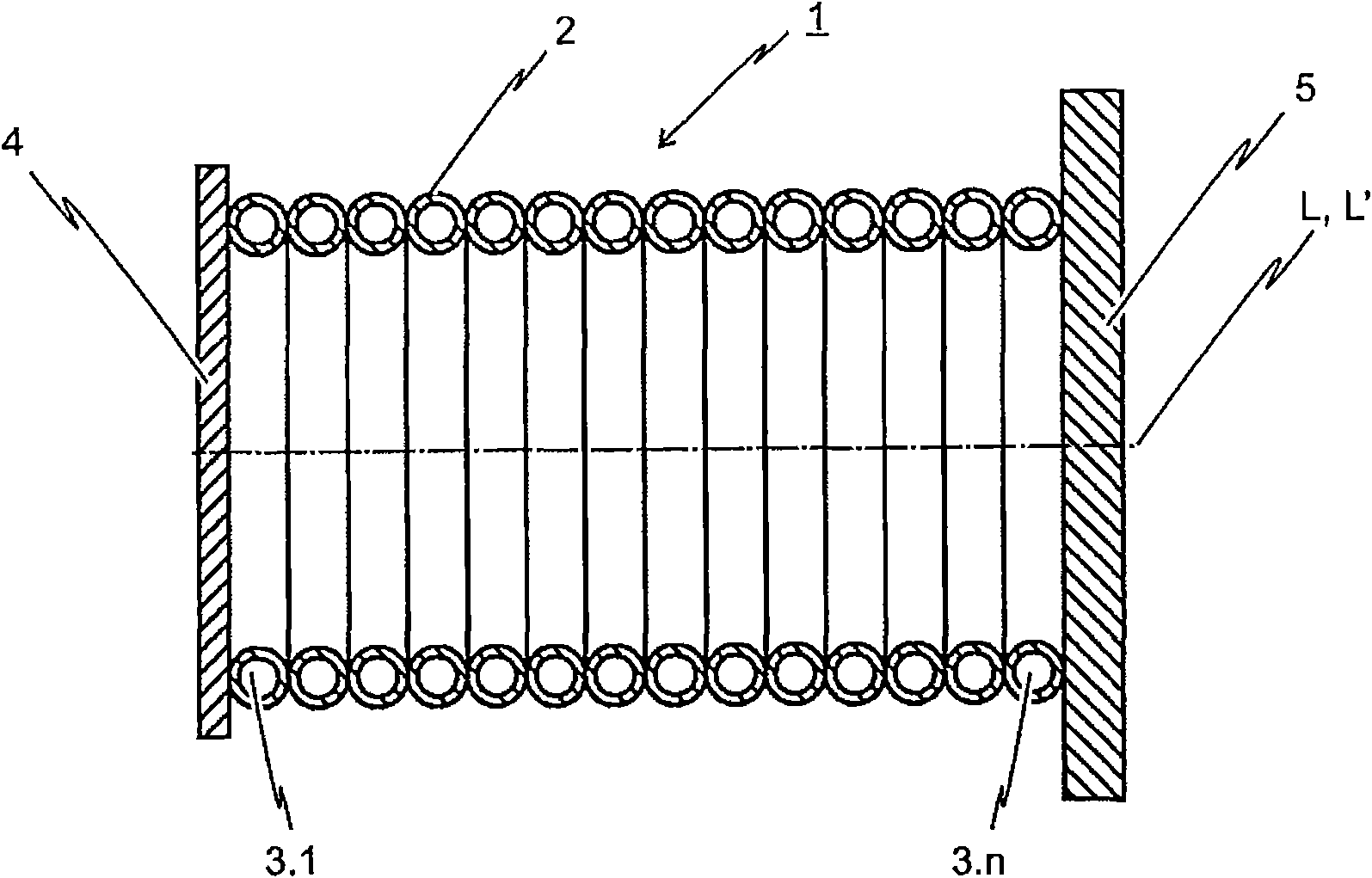
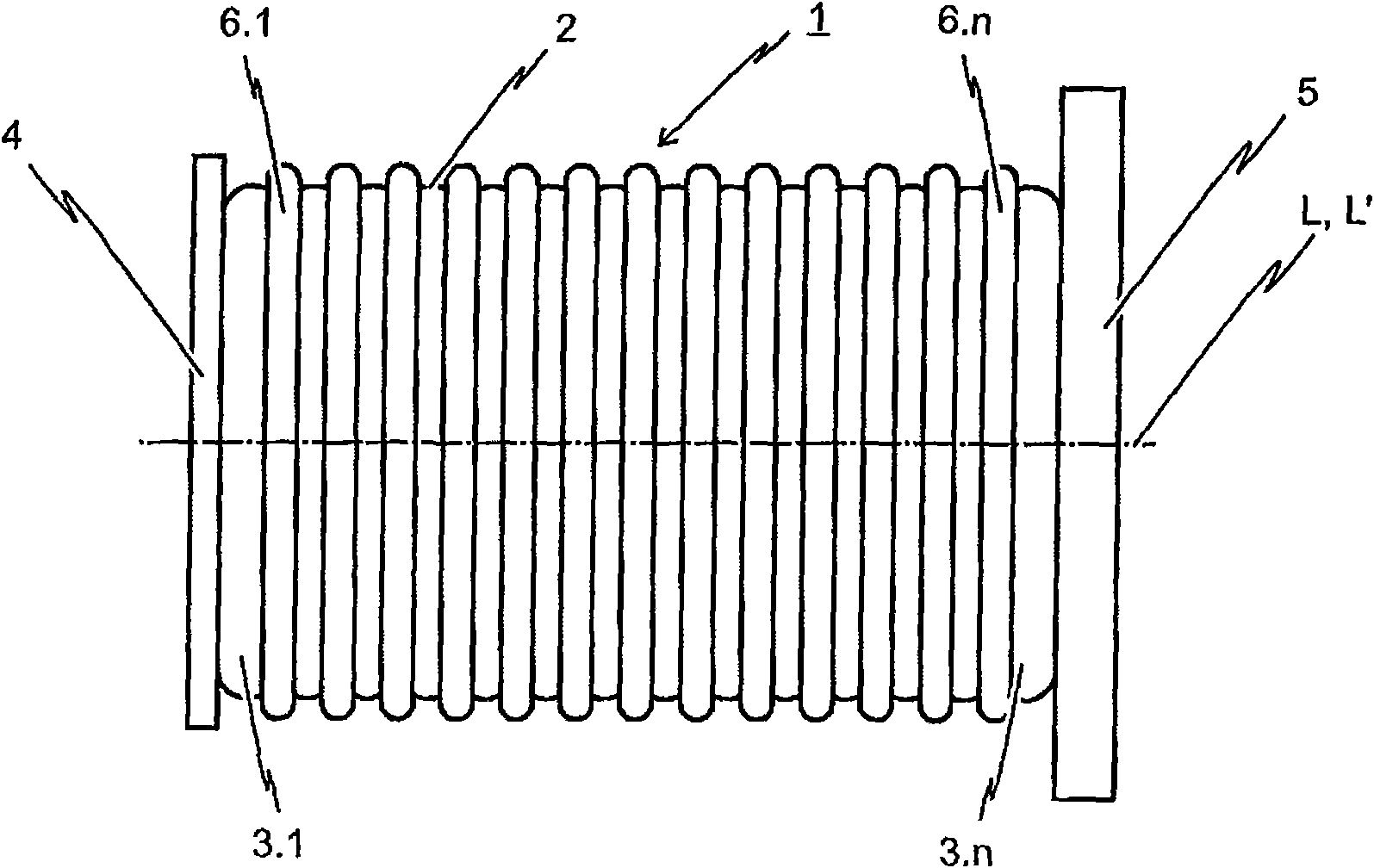
[0038] figure 1 A side view of a first embodiment of the invented energy dissipating element 1 is depicted. The energy dissipation element 1 is arranged between the force transmission element 4 and the base plate 5 such that the compressive force introduced into the force transmission element 4 is transmitted to the base plate 5 through the wall 2 of the energy dissipation element 1 . As depicted, the energy dissipating element 1 is configured in the form of a hollow body extending in the longitudinal direction L. As shown in FIG. The peripheral surface of the hollow body is formed by the wall 2 of the energy dissipating element 1 .

[0039] according to figure 1 A first embodiment of the inventive energy dissipating element 1 depicted in , the wall 2 of said energy dissipating element 1 is formed by a plurality of annular deformation elements 3.1 to 3.n. These annular deformation elements 3.1 to 3.n are arranged such that the axis of rotation L' of each annular deformation...


PUM


Abstract

An energy-dissipating element has the form of a hollow body extending in the longitudinal direction, wherein the element comprises a wall forming the peripheral surface of the hollow body. The element is designed to respond upon the exceeding of a critical impact force applied to a front of the element and to convert at least a portion of the impact energy ensuing from the transfer of the impact force through the element into the energy and heat of deformation by plastic deformation. In order to achieve the follow object that the residual block length is as small as possible in the available space, and therefore the energy-dissipating element can perform high enough of energy dissipation in the longitudinal axes of the predictable sequence of the response and event defined by the energy-dissipating element, the hollow body form a wall of the energy-dissipating element, based on that the inventive energy-dissipating element includes at least one deformation element formed along the appearance (specifically the hollow appearance) and extending long the longitudinal axes of the hollow body.

Description

technical field [0001] The invention relates to an energy dissipating element in the form of a longitudinally extending hollow body, wherein said energy dissipating element comprises a wall forming a peripheral surface of said hollow body, and wherein said energy dissipating element is designed to be applied beyond the The energy dissipating element responds after a critical impact force at the front end of the energy dissipating element, and absorbs at least a portion of the impact energy resulting from transmitting the impact force through the energy dissipating element by means of plastic deformation; that is, converts it into deformation energy and hot. The invention also relates to a shock absorber, in particular for use as a side bumper at the front end of a rail vehicle, such as a railway vehicle, or in a bump stop, wherein said shock absorber comprises an energy dissipating element of the above-mentioned type . Background technique [0002] Energy dissipating eleme...

Claims


Application Information

Patent Timeline
Patent Type & Authority Applications(China)
IPC IPC(8): B61G11/14
CPCB61G11/16F16F7/12B60R19/34
Inventor U·贝卡S·德罗贝克
Owner VOITH PATENT GMBH
Why Eureka
Try Eureka