
Blowing type gas water heater constant temperature control method and control system thereof

A gas water heater and constant temperature control technology, which is applied to fluid heaters, lighting and heating equipment, etc., can solve the problems of insufficient gas supply, unusable water heaters, and the water outlet temperature of the water heater cannot reach the set temperature, etc. The effect of load Q, reducing workload, and increasing air supply

Active Publication Date: 2010-09-22
GUANGDONG HUAMEI JUNDA ELECTRIC APPLIANCES
View PDF0 Cites 31 Cited by
  • Summary
  • Abstract
  • Description
  • Claims
  • Application Information

AI Technical Summary

Problems solved by technology

[0004] At present, the constant temperature control technology of domestic blast-type gas water heaters is based on a certain gas mixed with a certain proportion of air for combustion to achieve qualified combustion conditions. When the path of the gas path is not large enough or when the gas consumption is low, the gas supply is insufficient, so that the outlet water temperature of the water heater cannot reach the set temperature. The opening is increased, and the blast air volume is increased at the same time, but due to insufficient gas supply, the gas volume has not increased. In this way, when the blast air volume reaches a certain level, the flame will be blown out, causing the water heater to be unusable

Method used


Image

  • Blowing type gas water heater constant temperature control method and control system thereof
  • Blowing type gas water heater constant temperature control method and control system thereof
  • Blowing type gas water heater constant temperature control method and control system thereof

Examples


Embodiment Construction

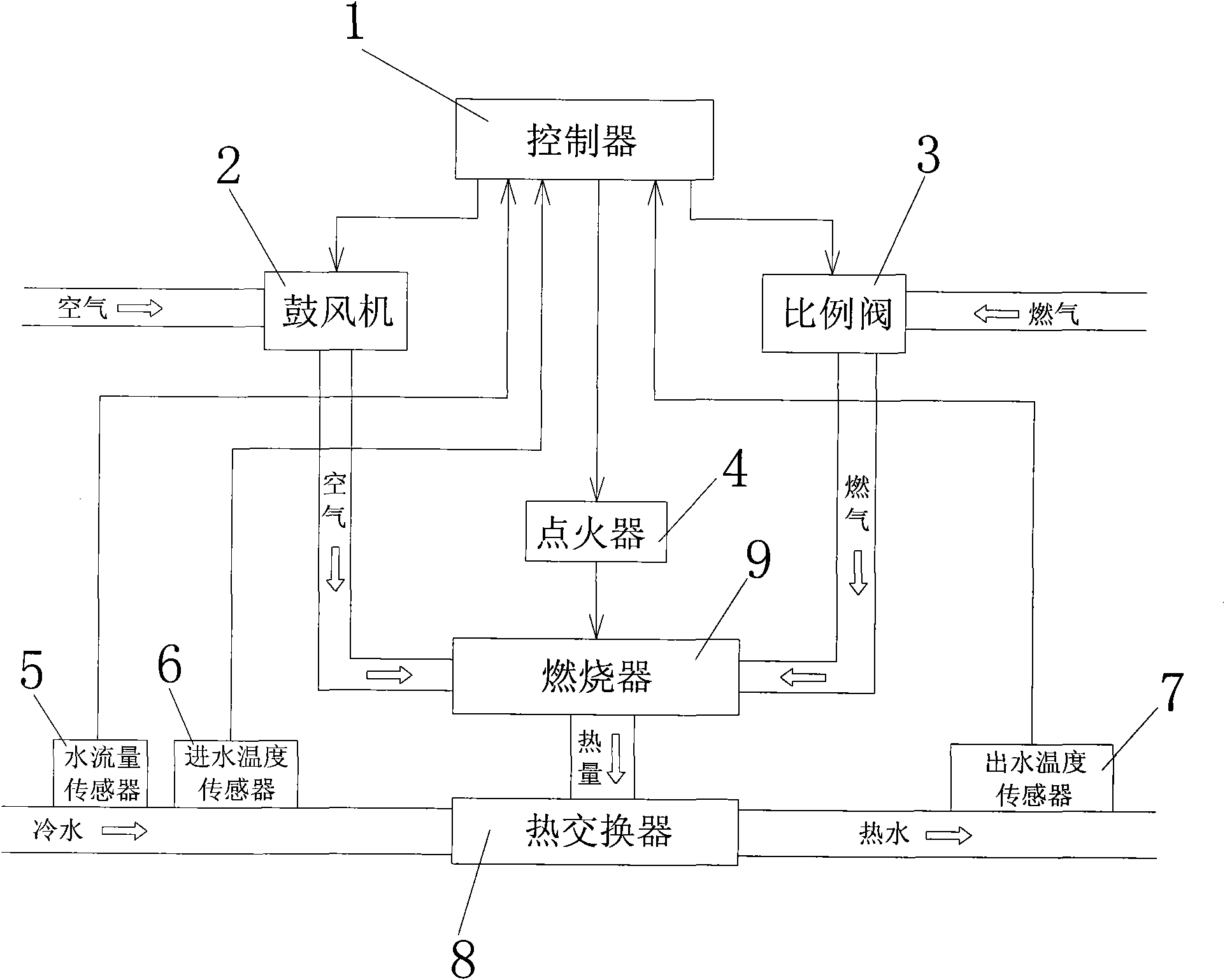
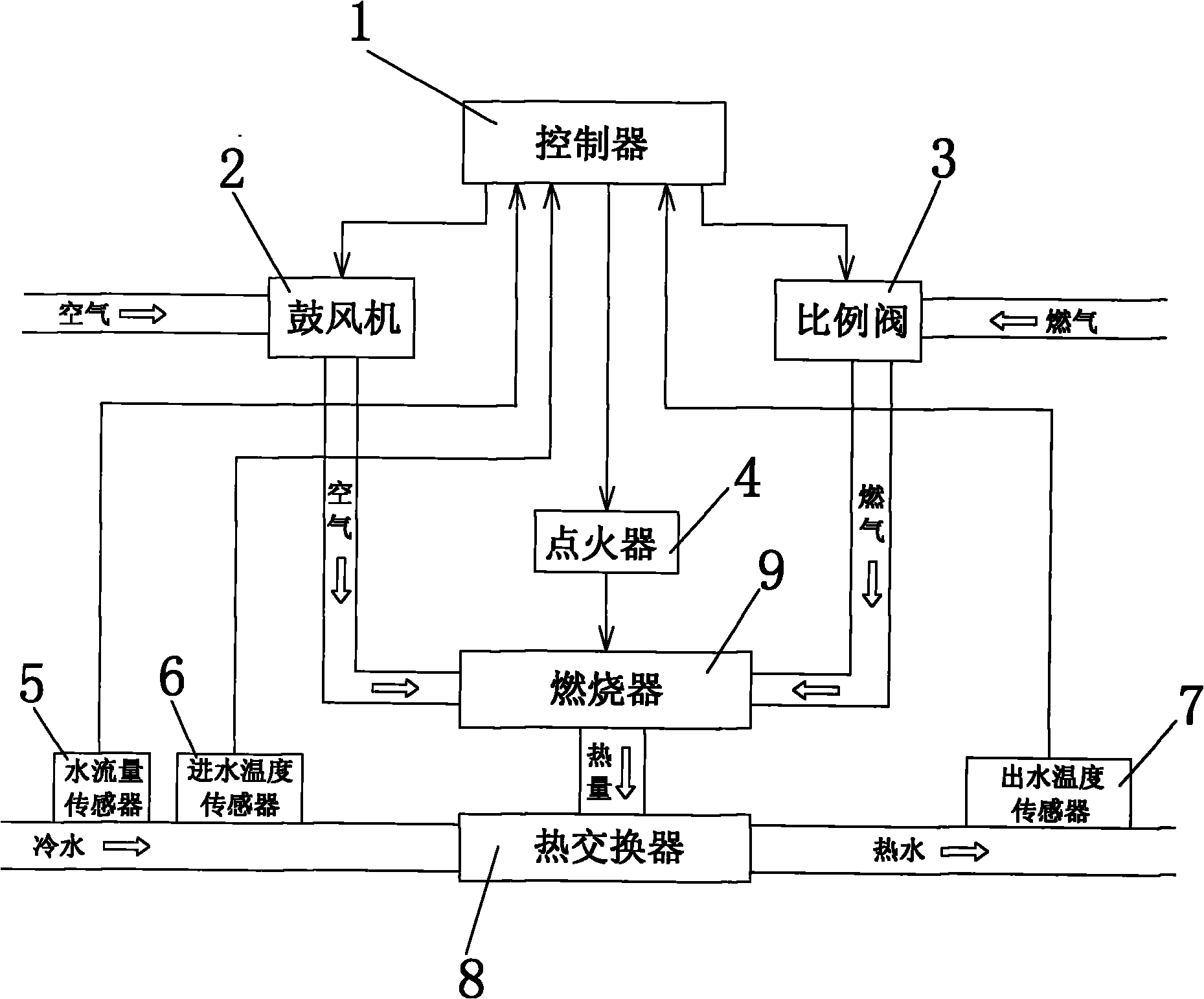
[0015] Such as figure 2 As shown, a constant temperature control system for a blast type gas water heater includes a central controller 1, a blower 2, a gas proportional valve 3, an igniter 4, a water flow sensor 5, an inlet water temperature sensor 6, and an outlet water temperature sensor 7. The output end of the controller 1 is electrically connected to the input end of the blower 2, the gas proportional valve 3 and the igniter 4, and the input end of the controller 1 is connected to the output ends of the water flow sensor 5, the water inlet temperature sensor 6 and the water outlet temperature sensor 7, The igniter 4 controls the burner 9 to enter the combustion state. When using the water heater, open the water valve, the water flow sensor 5 detects the water flow signal V, and transmits the water flow signal V to the controller 1, and the controller 1 according to the water flow signal V V starts the blower 2 and the igniter 4, and opens the gas proportional valve 3, s...


PUM


Abstract

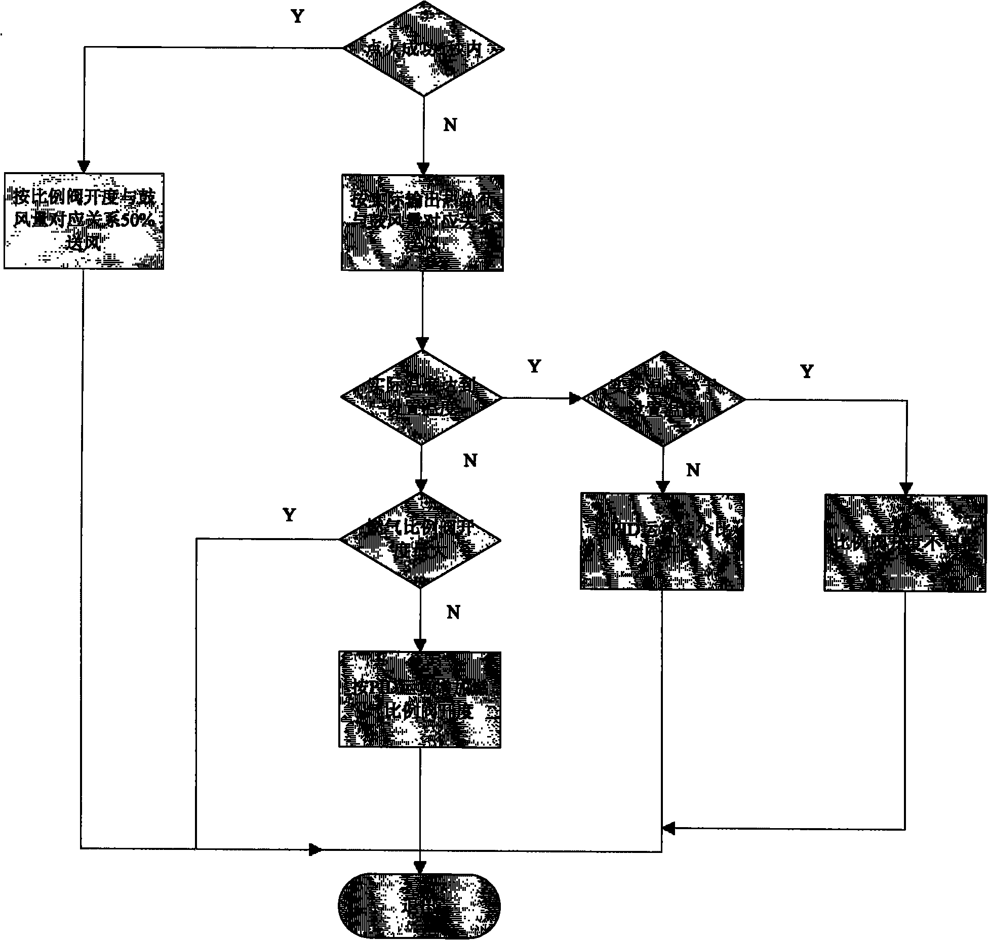
The invention relates to a blowing type gas water heater constant temperature control method, which is characterized in that after the water heater is successfully ignited, a controller calculates the current thermal load Q according to the water flow V, water inflowing temperature T0, water outflowing temperature T1 set by a user, calculates and controls the air quantity S output by an air flower according to the thermal load Q, guarantees the flame not to be blown out, and causes the heater to work when the gas supply is low. The blowing type gas water heater constant temperature control system comprises a central controller, the air blower, a gas proportional valve, an igniter, a water flow sensor, a water inflowing temperature sensor and a water outflowing temperature sensor; after the igniter is successfully ignited, the controller calculates and controls the air quantity S output by the air blower according to the thermal load Q; when the real water outflowing temperature T11 is less than the set water outflowing temperature T1, the controller controls the gas proportional valve to increase the openness of the valve thereof and the air demand of the gas passage so that the real water outflowing temperature T11 reaches the set water outflowing temperature T1. The invention causes that the heater can work when the gas supply quantity is low, can rapidly recover the constant temperature state when the gas supply quantity recovers, thus being convenient for users to use.

Description

[0001] Field: [0002] The invention relates to a constant temperature control method and a control system for a blast type gas water heater. Background technique: [0003] The traditional blower gas water heater control system includes a controller, blower, gas proportional valve, igniter and water outlet temperature sensor. The output of the controller is electrically connected to the input of the blower, gas proportional valve and igniter. The input end is electrically connected to the output end of the water outlet temperature sensor, the igniter controls the burner to enter the combustion state, the blower and the gas proportional valve respectively send air and gas into the burner for mixed combustion, and the burner transfers the heat generated to the heat exchanger , the cold water turns into hot water after passing through the heat exchanger, thus generating hot water supply. [0004] At present, the constant temperature control technology of domestic blast-type gas ...

Claims


Application Information

Patent Timeline
IPC IPC(8): F24H9/20
Inventor 张健明
Owner GUANGDONG HUAMEI JUNDA ELECTRIC APPLIANCES
Learn More