Plate cavity-type heat exchanger

A heat exchanger and plate cavity technology, which is applied in the field of plate cavity type phase change heat exchange devices, can solve the problem that the thermal conductivity is not very high, it is difficult to meet higher pressure requirements, and the flow space of the heat carrier in the flow space of the working fluid cavity is limited. and other problems, to achieve the effect of improving heat exchange efficiency, improving pressure bearing performance, and reducing pressure bearing requirements

Inactive Publication Date: 2012-05-23
湖北拓博热力科技有限责任公司
View PDF0 Cites 0 Cited by
  • Summary
  • Abstract
  • Description
  • Claims
  • Application Information

AI Technical Summary

Problems solved by technology

[0002] In heat exchange devices, the most common are tube heat exchangers and plate heat exchangers. The main structure of plate heat exchangers is: in order to increase the heat exchange area, a heat exchange plate with a corrugated cross section (the described The waveform can be corrugated, triangular or rectangular, etc.), on both sides of the corrugated heat exchange plate, there are respectively a working medium fluid chamber and a heat transfer fluid chamber, and the working fluid and heat transfer fluid chambers of different temperatures flow through the chambers on both sides. Fluid, heat exchange is realized through the corrugated heat exchange plate. Due to the large heat exchange area of ​​the plate heat exchanger, its heat exchange efficiency is also higher than that of the tube heat exchanger, but because the working medium fluid chamber of the heat exchanger has to withstand higher Therefore, for plate heat exchangers, there is also the problem that it is difficult to meet higher pressure bearing requirements. In order to improve the pressure bearing capacity of heat exchangers, most of the existing plate heat exchangers are designed from the pressure bearing performance of materials. Start: The heat exchange wave plates that make up the working medium cavity are made of materials with good pressure bearing performance, and some materials with high pressure bearing capacity, such as stainless steel, have good pressure bearing performance, but the thermal conductivity is not very high, especially the existing plate type The multi-point contact pressure-bearing structure between the wave plates used in the heat exchanger limits the flow space of the working medium fluid chamber and the flow rate of the heat carrier

Method used


Image

  • Plate cavity-type heat exchanger
  • Plate cavity-type heat exchanger
  • Plate cavity-type heat exchanger

Examples


Embodiment Construction

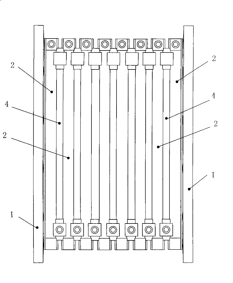
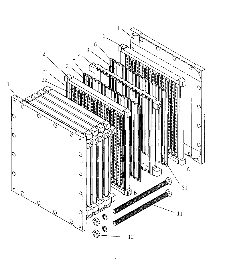
[0026] see figure 1 , figure 2 , In this example, there are 6 heat exchange units sandwiched between a pair of compression plates 1 . Each heat exchange unit includes a cavity frame 4, two heat exchange wave plates 3, and two water plates 2, and adjacent heat exchange units can share one water plate. The two pressing plates 1 are connected by fastening bolts 11 and fastening nuts 12, so as to press and connect the components of each heat exchange unit as a whole.

[0027] see figure 2 , is a schematic diagram of the split state structure of a heat exchange unit adjacent to the compression plate 1:

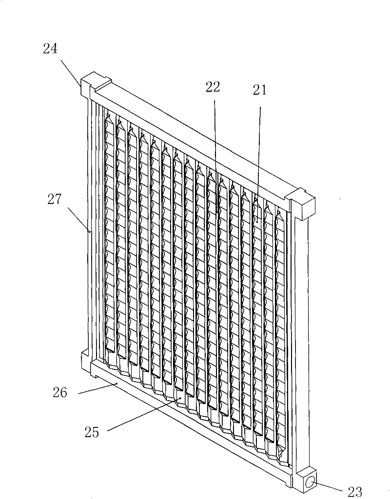
[0028] The cross-sections of the two corrugated plates 3 opposite to each other are triangular waveforms, the two sides of the corrugated plates present longitudinal corrugated grooves arranged side by side, and the directions of the corrugated corrugated grooves 31 on the two corrugated plates are consistent;

[0029] The cross-section of the wave plate can also be sinusoida...


PUM


Abstract

The invention relates to a plate cavity-type heat exchanger which is provided with a plurality of heat exchange units clamped between two pressure plates (1); each heat exchange unit is respectively provided with two opposite wave plates (3) with wavy cross section; bifarius surfaces of the two wave plates are respectively opposite to water plates (2) on the corresponding sides; the water plates are provided with a plurality of horizontal water plate wave troughs (21) which are vertical to longitudinal wave plate wave troughs (31) on plane surfaces opposite to the wave plates, and a pluralityof longitudinal pressure bearing strips (22); all the pressure bearing strips respectively correspond to the trough parts of the wave plate wave troughs; a cavity frame (4) is arranged between the two water plates; the front side and the rear side of the side frame of the cavity frame are respectively inlaid in the water plates (2, 6) on the corresponding sides, and respectively seal and press the periphery of the wave plate (3) on the corresponding side to the corresponding water plate through the side frame; and the invention can improve the pressure bearing capability of the heat exchangerand reduce the pressure bearing requirement on the heat exchange wave plates, the size of the working substance cavity can be designed on demand, and the problems that impurities block a runner and the like can be overcome by enlarging the cross section of the heat carrying runner.

Description

technical field [0001] The invention belongs to a heat exchange device, in particular to a plate cavity type phase change heat exchange device. Background technique [0002] In heat exchange devices, the most common are tube heat exchangers and plate heat exchangers. The main structure of plate heat exchangers is: in order to increase the heat exchange area, a heat exchange plate with a corrugated cross section (the described The waveform can be corrugated, triangular or rectangular, etc.), on both sides of the corrugated heat exchange plate, there are respectively a working medium fluid chamber and a heat transfer fluid chamber, and the working fluid and heat transfer fluid chambers of different temperatures flow through the chambers on both sides. Fluid, heat exchange is realized through the corrugated heat exchange plate. Due to the large heat exchange area of ​​the plate heat exchanger, its heat exchange efficiency is also higher than that of the tube heat exchanger, but...

Claims


Application Information

Patent Timeline
Patent Type & Authority Patents(China)
IPC IPC(8): F28D9/00F28F3/08F28F3/04F28F9/007F28F13/12F28F3/10F28F21/08F28F19/02
Inventor 许欣平
Owner 湖北拓博热力科技有限责任公司
Why Eureka
Try Eureka