Pedestrian protection airbag device

A technology of pedestrian protection and airbags, which is applied in pedestrian/occupant safety arrangement, transportation and packaging, vehicle safety arrangement, etc., can solve the problems of time limitation, achieve the effects of simplifying structure, improving space efficiency and reducing the number of parts

Active Publication Date: 2010-09-22
HONDA MOTOR CO LTD
View PDF1 Cites 6 Cited by
  • Summary
  • Abstract
  • Description
  • Claims
  • Application Information

AI Technical Summary

Problems solved by technology

[0004] However, the time it takes for the pedestrian's head to be thrown above the hood by the vehicle to collide with the front pillar varies according to the speed of the vehicle at the time of the collision and the shape of the pedestrian. Exhausted from the exhaust hole and shrunk, the time to exert the shock absorbing ability is limited, and it is difficult to exert effective shock absorbing ability regardless of the vehicle speed at the time of collision and the body shape of the pedestrian.

Method used


Image

  • Pedestrian protection airbag device
  • Pedestrian protection airbag device
  • Pedestrian protection airbag device

Examples


no. 1 approach

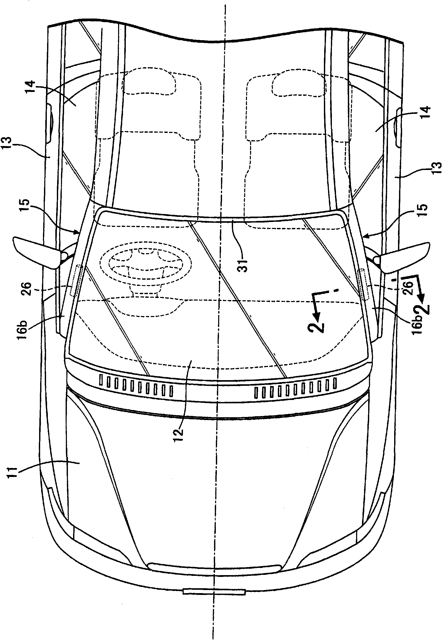
[0059] Figure 1 ~ Figure 4 The first embodiment of the present invention is shown.

[0060] Such as figure 1 As shown, the automobile has a front windshield 12 behind the hood 11, and the front pillars 15, 15 are configured to be clamped between the left and right edges of the front windshield 12 and the door glasses 14, 14 of the front doors 13, 13. between.

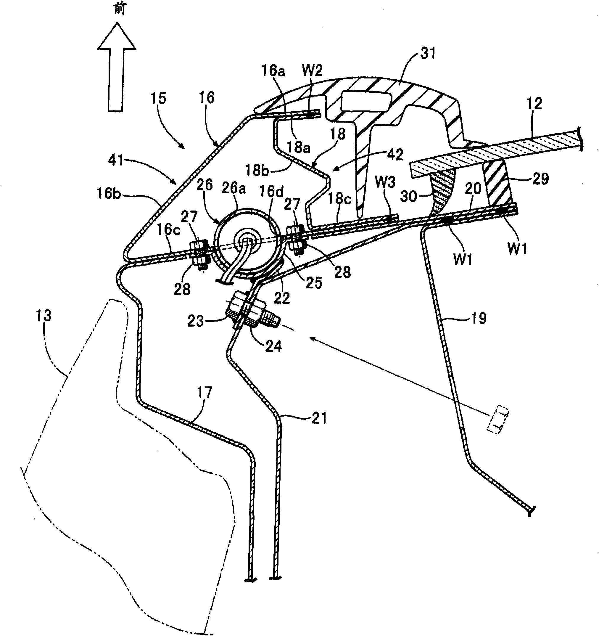
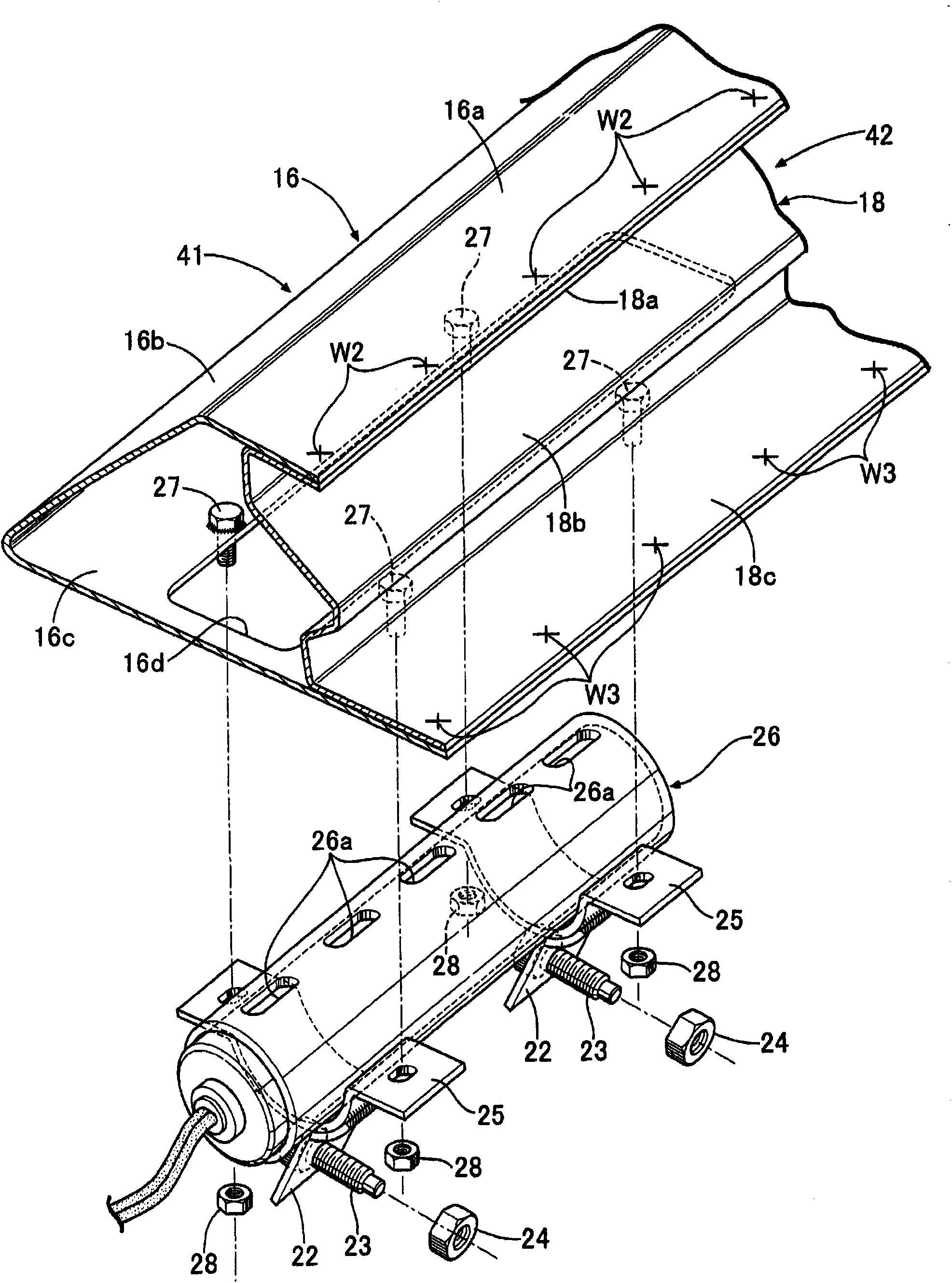
[0061] Such as figure 2 As shown, the front pillar 15 of this embodiment has: a front outer panel 16 and a rear outer panel 17 located on the outer side of the vehicle body, a front inner panel 18 and a rear inner panel 19 located on the inner side of the vehicle body, and the four panels 16 ~ 19 are connected and strengthened front reinforcing plate 20 and rear reinforcing plate 21.

[0062] The inner ends in the vehicle width direction of the rear inner panel 19 , the rear reinforcement panel 21 , and the front reinforcement panel 20 are spot-welded to W1 and W1 so that they overlap in three layers. The front o...

no. 2 approach

[0075] Figure 5 and Figure 6 The second embodiment of the present invention is shown.

[0076] In the second embodiment, the rear edge 16c of the front outer panel 16 of the first embodiment is constituted by an intermediate panel 32 which is a member different from the decorative surface 16b. The outer end in the vehicle width direction of the intermediate panel 32 overlaps the rear end of the decorative surface 16b of the front outer panel 16 and is welded to W4. Then, the intermediate panel 32 near the welding point W4 is bent in a triangular shape to form a curved portion 32a, and the front end of the flat portion 32b extending inward in the vehicle width direction from the curved portion 32a is welded to the rear of the front inner panel 18 at W3. On the edge 18c of the flat portion 32b, the inflator 26 is fitted into an opening 32c formed in the middle of the flat portion 32b. A rubber lip 33 is attached to a connection portion between the rear end of the front oute...

no. 3 approach

[0079] Figure 7 and Figure 8 The third embodiment of the present invention is shown.

[0080] In the third embodiment, the airbag 34 constituting a part of the front pillar 15 is integrally formed as a single metal member by roll forming. The airbag 34 has a closed cross section with its end edge welded to W5, and has an exposed portion 41 exposed outside the vehicle body so as to cover between the outer edge in the vehicle width direction of the front windshield 12 and the front edge of the front door 13. , and the stretching portion 42 that is hidden behind the exposed portion 41 in an invisible manner and bends in a stretchable manner. The surface of the exposed part 41 formed in an arc-shaped cross section is a decorative surface 41a, and is arranged to fit smoothly between the front windshield 12 and the outer edge in the vehicle width direction and the front edge of the front door 13 in line with the trim 31. connect. On the other hand, an opening 42a into which th...


PUM


Abstract

A pedestrian protection airbag device in which an airbag (34) having a closed cross-section is formed by inflating and expanding a front outer panel (16) and a front inner panel (18) of a front pillar (15) by high-pressure gas discharged from an inflator (26). This protects the head of a pedestrian from an impact due to collision of the head against the front pillar (15). Because the expanded airbag (34) exhibits its impact absorption performance when it plastically deforms, so long as the airbag (34) completes expansion until it retains the pedestrian, subsequent control of the inner pressure of the airbag (34) is not required. The construction simplifies specifications of the inflator (26) to reduce costs, and the airbag device can always exhibit effective impact absorption performance regardless of the vehicle speed at the time of collision and the body build of the pedestrian.

Description

technical field [0001] The present invention relates to a pedestrian airbag device for protecting a pedestrian colliding with a vehicle from impact by using an airbag made of a metal material. Background technique [0002] In order to protect pedestrians who are thrown by the vehicle onto the hood from impact, the rear end of the hood is raised slightly to form a crushing space for shock absorption. The technology of deploying the front pillars of the windshield and deploying the crack prevention film covering the front surface of the windshield between the left and right pillar airbags is known in the following patent document 1. [0003] Patent Document 1: Japanese Patent Laid-Open No. 2000-264146 [0004] However, the time it takes for the pedestrian's head to be thrown above the hood by the vehicle to collide with the front pillar varies according to the speed of the vehicle at the time of the collision and the shape of the pedestrian. Exhausted from the exhaust hole a...

Claims


Application Information

Patent Timeline
Patent Type & Authority Applications(China)
IPC IPC(8): B60R21/34B62D25/04B60R21/16B60R13/04B60R21/36
CPCB60R2021/23528B60R21/36
Inventor 冈本丰菊池裕二上地幸一
Owner HONDA MOTOR CO LTD
Why Eureka
Try Eureka