Cloth bonding apparatus

A technology of cloth bonding and adhesive, which is applied in the field of cloth bonding devices, can solve the problems of gas removal, complicated device structure, and inability to remove gas efficiently, and achieve the effect of suppressing gas concentration

Inactive Publication Date: 2010-09-29
BROTHER KOGYO KK
View PDF0 Cites 11 Cited by
  • Summary
  • Abstract
  • Description
  • Claims
  • Application Information

AI Technical Summary

Problems solved by technology

[0004] The device described in the above publication has a complex structure and cannot remove the gas according to the gas generation condition
Therefore, the device described in the above publication cannot efficiently remove the gas generated from the molten adhesive.

Method used


Image

  • Cloth bonding apparatus
  • Cloth bonding apparatus
  • Cloth bonding apparatus

Examples


Embodiment Construction

[0020] Next, the cloth bonding apparatus 1 of the present invention will be described with reference to the drawings.

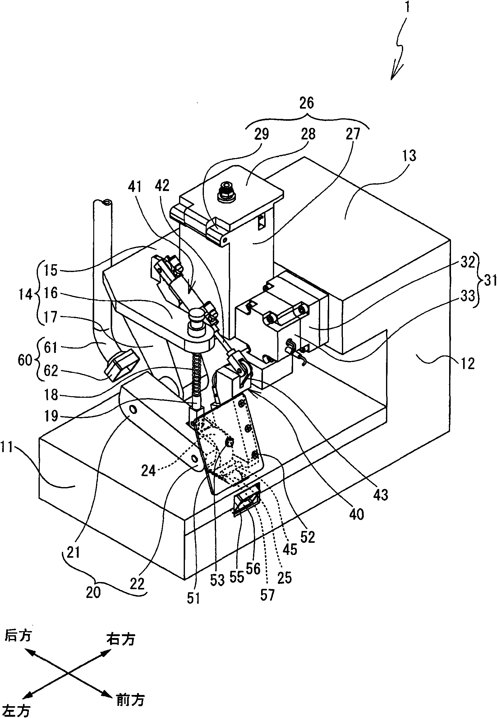
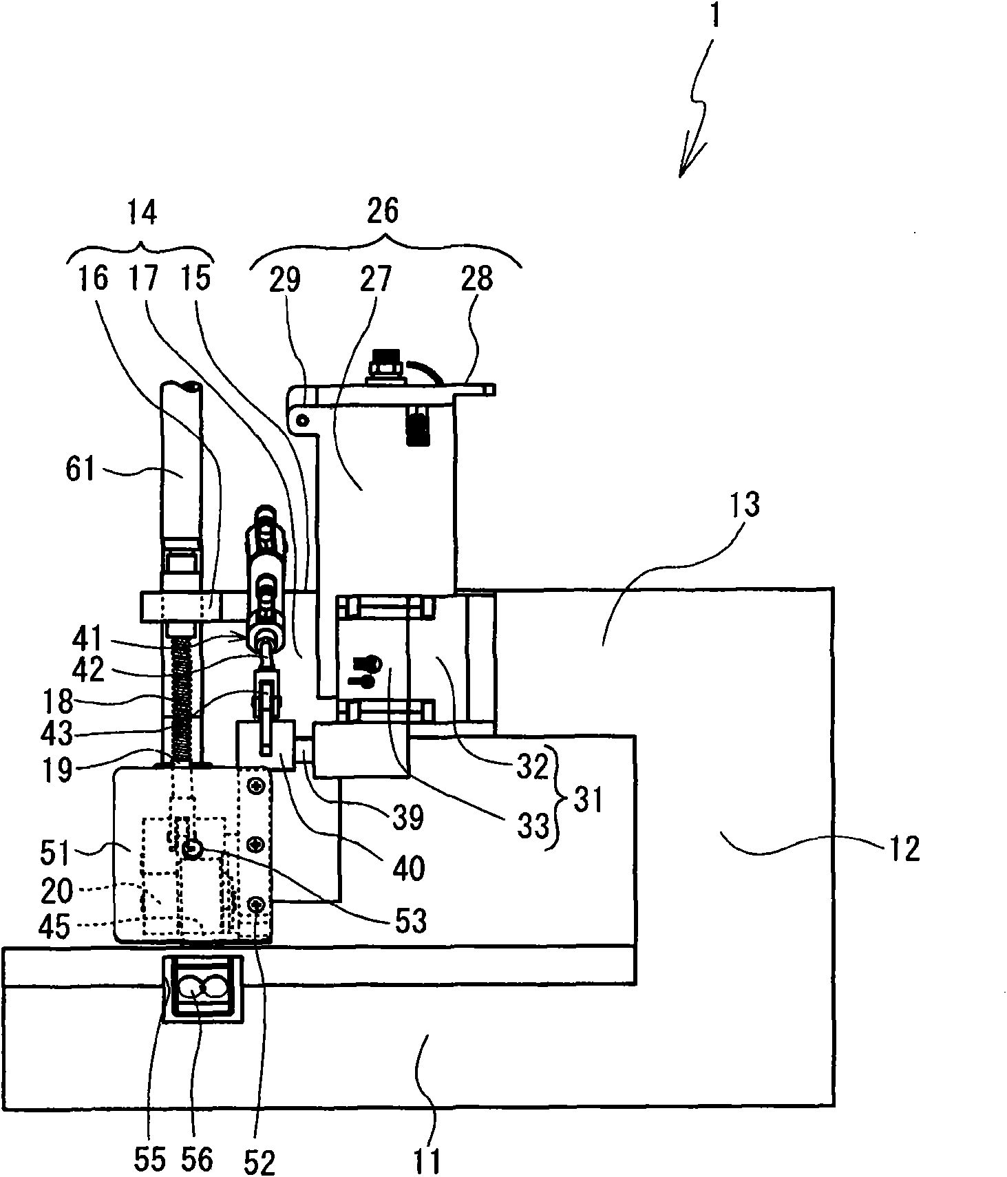
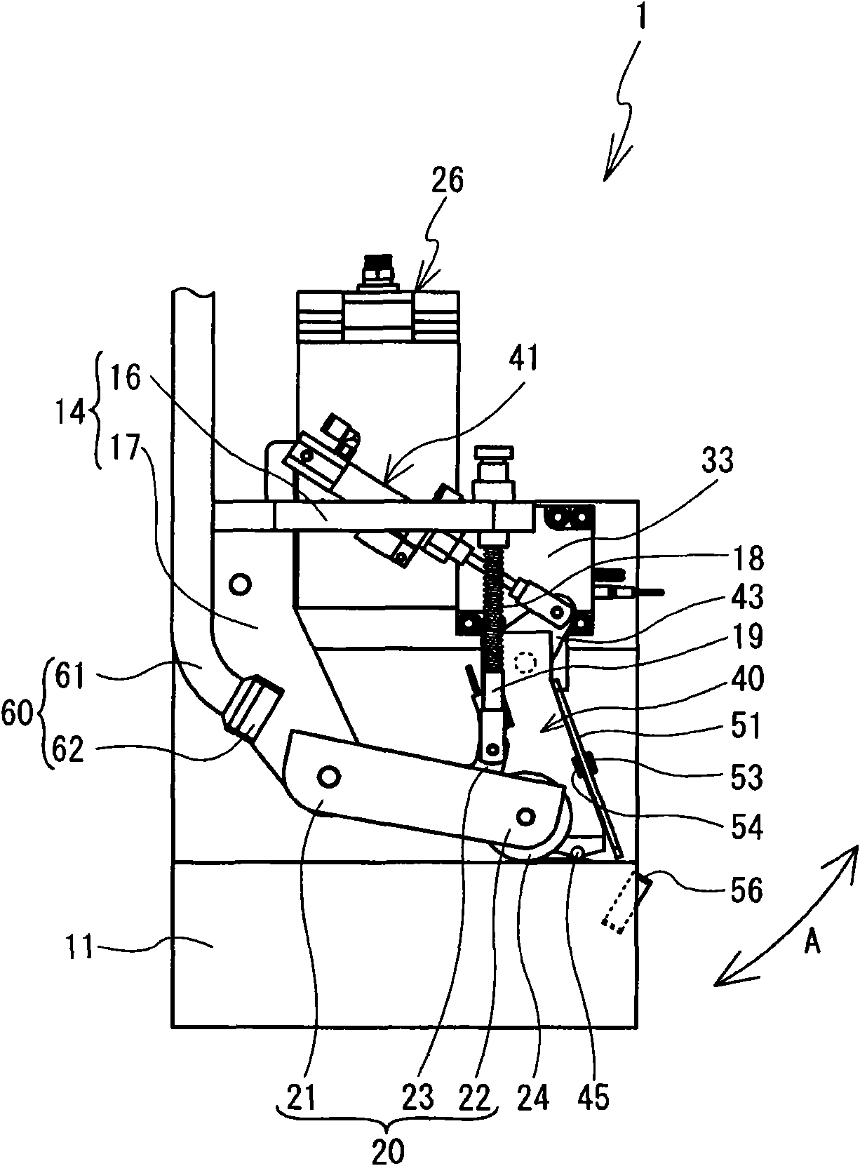
[0021] refer to Figure 1~3 , the structure of the cloth bonding apparatus 1 will be described. Will figure 1 Right obliquely lower, left obliquely upper, right obliquely upper, and left obliquely lower as the front, rear, right, and left of the cloth bonding apparatus 1, respectively.

[0022] Such as figure 1 and figure 2 As shown, the cloth bonding device 1 includes: a base part 11 , a column part 12 , and an arm part 13 . The base portion 11 has a substantially rectangular parallelepiped shape whose longitudinal direction is the left-right direction. The base portion 11 is fixed to a table (not shown). The pillar portion 12 extends vertically upward from the right end of the base portion 11 . The arm portion 13 is connected to the upper end of the column portion 12 and protrudes to the left of the left side surface of the column portion 12 .

[0...


PUM


Abstract

A cloth bonding apparatus 1 includes a nozzle 45 through which an adhesive is dischargeable onto a cloth. A plate-shaped covering member 51 is positioned between the nozzle 45 and a worker, thereby preventing gas from directly flowing from the nozzle 45 toward a worker side. The covering member 51 includes first and second gas sensors 53, 54. A bed portion 11 includes a blower fan 56 that takes in air from the worker side through an opening 55 and blows the air through an opening 57 toward the nozzle 45. A CPU increases an output power of the blower fan 56, if at least one of gas concentrations detected by the first and second gas sensors 53, 54 is equal to or more than a predetermined value. Therefore, the cloth bonding apparatus 1 can efficiently remove the gas generated from the adhesive discharged from the nozzle 45.

Description

technical field [0001] The invention relates to a cloth bonding device. More specifically, the present invention relates to a cloth bonding device that adheres cloth to cloth by attaching an adhesive to cloth and pressing them together. Background technique [0002] The cloth bonding device does not use needles and stitches to sew cloth, but uses adhesive to bond cloth to cloth. The cloth bonding device heats and melts the adhesive solidified at normal temperature, and discharges the melted liquid adhesive from the nozzle to make it adhere to the cloth. The cloth bonding apparatus pressurizes and transfers the cloth with the adhesive attached thereto using a roller, thereby bonding the cloth to the cloth. Since the bonded cloth does not use stitches, no unevenness occurs on the cloth. In such a cloth bonding apparatus, the molten adhesive discharged from the nozzle may generate gas. Therefore, in such a cloth bonding apparatus, it is desirable to remove the gas in order ...

Claims


Application Information

Patent Timeline
Patent Type & Authority Applications(China)
IPC IPC(8): A41H43/04
CPCB29K2313/00B29C66/934B29C66/83431B29C66/8161B29C66/9141B29C66/9672B29C66/91641B29C66/80B29C66/9121B29C66/8762B29C66/872B29C66/96B29C66/8167B29C66/90B29C65/4815B29C66/9674B29C66/002B29C65/524B29C66/845B29C66/91212B29C66/8742B29C66/91231B29C66/91431B29C66/729B29C66/43B29C66/8221B29C66/8242B29C66/8324B29C66/932B29C66/93451B29C66/961
Inventor 山浦宏贵梅田和俊岩越弘恭盐谷哲司多田悟吉本直树大村义和
Owner BROTHER KOGYO KK
Why Eureka
Try Eureka