Scalp clip gun

A scalp clip and machine head technology, applied in the field of medical equipment, can solve the problem of inconvenient use of the scalp clip for doctors, and achieve the effects of simple structure, improved work efficiency, and convenient operation

Active Publication Date: 2010-09-29
BEIJING HONGHU GAO XIANG TECH
View PDF8 Cites 17 Cited by
  • Summary
  • Abstract
  • Description
  • Claims
  • Application Information

AI Technical Summary

Problems solved by technology

[0003] The purpose of the present invention is to propose a technical scheme of a scalp clip gun, the scalp clip gun adopts a clip m

Method used


Image

  • Scalp clip gun
  • Scalp clip gun
  • Scalp clip gun

Examples


Embodiment 1

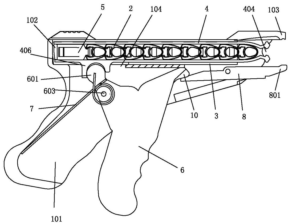
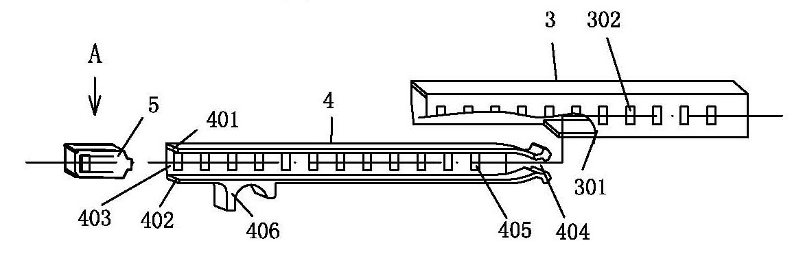
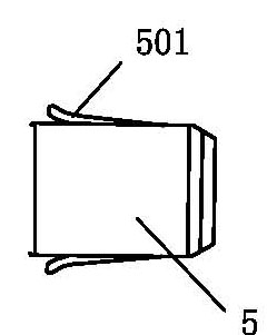
[0022] A kind of scalp clip gun embodiment, see figure 1 , figure 2 with image 3 , the scalp clip gun includes a housing 1 with a handle 101, a clip bin for storing the scalp clip, a push clip mechanism for forward clipping and a clamping mechanism for promoting the scalp clip to open; the shell The body is provided with a magazine 102, the magazine is above the handle, the clip is snapped into the magazine, and the pushing and clamping mechanism and the opening and closing mechanism are arranged below the magazine; the clip includes a sliding sleeve 3, a clip holder 4 and Elastic card 5; one side 301 of the sliding sleeve is equidistantly provided with a plurality of holes 302 in the length direction of the sliding sleeve, and the holder is a long groove body with a U-shaped cross section, and the holder includes The upper side 401, the lower side 402, the bottom surface 403 and the clamping mouth 404, the bottom surface of the long tank body is provided with a plurality ...

Embodiment 2

[0030] Preferred embodiment of the scalp clip gun, see embodiment 1 and Figure 4 , the seesaw can be directly connected to the trigger tail box, but for more convenient operation, the other end of the seesaw described in this example is connected to the trigger through a trigger 9, and one end of the trigger is rotated by a pivot pin 901 Fixed on the shell, a roller 902 is set in the middle section of the trigger, the end surface of the trigger tail is a spiral arc surface 603 facing the trigger fixed shaft pin, and the spiral arc surface of the trigger tail is abutted on the roller , there is a connection gap 10 between the seesaw and the trigger, and the distance of the gap is the distance that the trigger pulls the holder into place; this structure can realize two consecutive steps of clip feeding and clip opening, which can make the doctor more delicate The feel controls the movement and opening of the scalp clip.

Embodiment 3

[0032] Another preferred embodiment of the scalp clip gun, see embodiment 1 and Figure 4 In order to reduce the arc that the front end of the seesaw moves upward when the scalp wallet is opened, because the large arc is likely to cause the front end of the seesaw to slip with the scalp wallet, the seesaw in this embodiment includes a front seesaw 11 and a The rear rocker 12 is two rockers, and the two rockers are fixed on the housing through two shaft pins that are misplaced front and rear. One end of the rear rocker is buckled with one end of the trigger, and the other end of the rear rocker supports the front rocker.

[0033] The working principle of the scalp gun is:


PUM


Abstract

The invention relates to a scalp clip gun, which comprises a shell with a handle, a clip chamber for storing a scalp clip, a clip pushing mechanism for feeding the clip forwards and a clip expanding mechanism for expanding the scalp clip, wherein the clip chamber comprises a sliding sleeve, a clip holder and an elastic card; one lateral surface of the sliding sleeve is provided with a plurality of holes in equal distance; the bottom surface of the clip holder is provided with a plurality of holes in equal distance; the clip holder is inserted into the sliding sleeve; an opening of the clip holder in the sliding sleeve faces the hole lateral surface of the sliding sleeve; and the elastic card has two outwards protruded elastic angles, the elastic card is arranged in a U-shaped groove of the clip holder, and the two elastic angles on the elastic card are blocked into the hole formed on the sliding sleeve and the hole on the lateral surface of the chip holder respectively. For the prior art, the scalp clip gun has the advantages of continuously taking out scalps clipped by the scalp clip, improving the work efficiency by over 50 percent, ensuring cleanness and no secondary pollution of the scalp clip by adopting alternated use of a plurality of clip holders and storing a plurality of scalp clips at one time, and having simple structure and convenient use and operation.

Description

technical field [0001] The invention belongs to medical apparatus and instruments, and in particular relates to a scalp clip gun. The scalp clip gun uses a magazine to transport scalp clips, which is convenient and hygienic, and solves the problem of inconvenient use of scalp clips by doctors. Background technique [0002] At present, scalp hemostasis in craniocerebral surgery in hospitals is achieved by using scalp clips. The function of scalp clips is to fix the scalp tissue so that it does not separate from the skull and prevent it from bleeding. Multiple scalp clips are used at the same time for a craniocerebral operation, usually The most common situation is that the doctor takes one and clips one during the operation, and the speed is relatively slow, but the actual situation is that the scalp needs to be clipped as soon as possible after the craniotomy, otherwise the patient's bleeding volume will increase, and excessive bleeding will increase the The nurse's clean-up...

Claims


Application Information

Patent Timeline
IPC IPC(8): A61B17/128
CPCA61B17/128A61B17/1227
Inventor 王凤吉王兵
Owner BEIJING HONGHU GAO XIANG TECH
Why Eureka
Try Eureka