Arc striking control method for double-electrode electric arc welding

A technology of arc welding and control method, which is applied in the direction of arc welding equipment, welding equipment, manufacturing tools, etc. It can solve the problems of shallow penetration, poor edge of weld bead, and decline of mechanical properties of welding parts, so as to maintain welding state, penetration and Appropriate cross-section shape of weld bead and the effect of stable welding state

Inactive Publication Date: 2014-09-10
DAIHEN CORP
View PDF4 Cites 0 Cited by
  • Summary
  • Abstract
  • Description
  • Claims
  • Application Information

AI Technical Summary

Problems solved by technology

However, when the arc is started, the heat input to the base material is insufficient, so the penetration depth of the arc starting part is shallow, and the cross-sectional shape of the weld bead becomes convex.
When the cross-sectional shape of the weld bead becomes convex, the fusion of the edge of the weld bead will be poor, so the mechanical properties of the welded part will decrease
Furthermore, the appearance of the weld bead is not beautiful
In addition, since two-electrode arc welding has two pyrogens, it is mostly used at a relatively fast welding speed. In this high-speed welding, the above-mentioned problems are more significant.

Method used


Image

  • Arc striking control method for double-electrode electric arc welding
  • Arc striking control method for double-electrode electric arc welding
  • Arc striking control method for double-electrode electric arc welding

Examples


no. 1 Embodiment approach

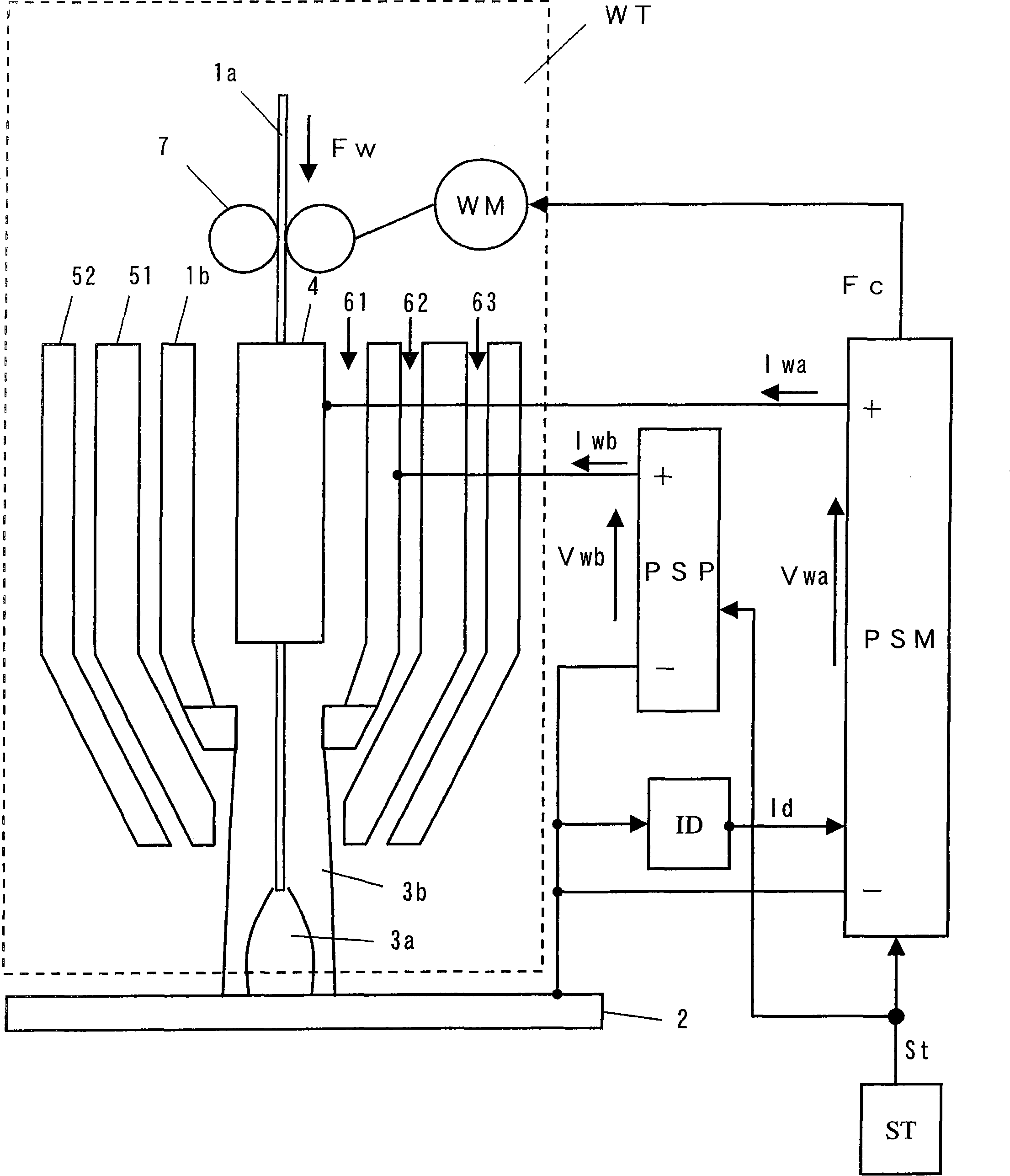
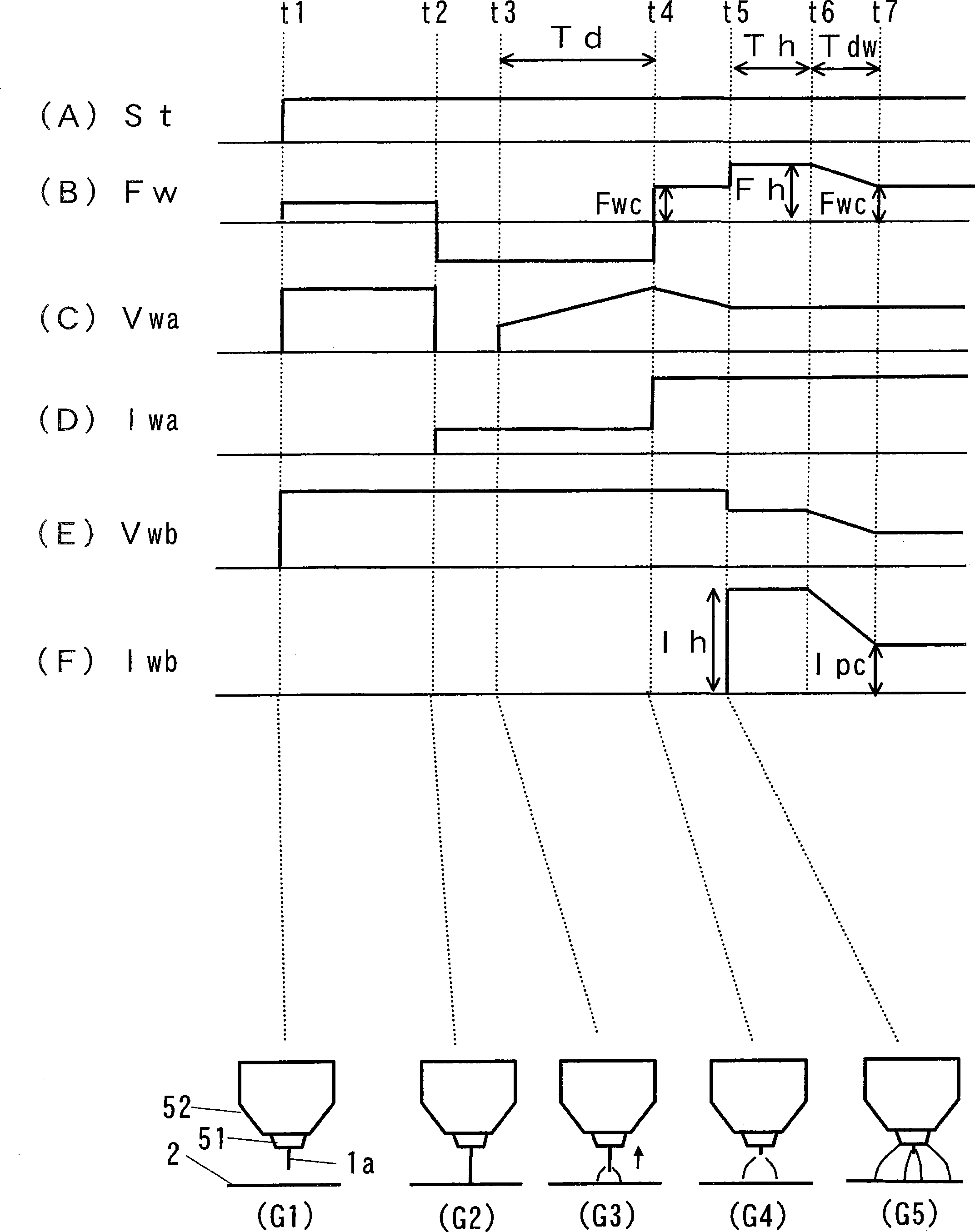
[0035] figure 1 It is a configuration diagram of a welding device for implementing the arc start control method of two-electrode arc welding according to the first embodiment of the present invention. This figure is similar to the above Figure 4 Correspondingly, for the same components, the same symbols are given, and no more details are given. The graph is in Figure 4 Add current detection circuit ID. Furthermore, the following uses figure 2 Describe the program control of the melting electrode arc welding power supply PSM and the non-melting electrode arc welding power supply PSP shown in the figure. Figure 5 different.

[0036] After the current detection circuit ID detects the non-melting electrode arc welding current Iwb, the current detection signal Id is input to the melting electrode arc welding power source PSM. The reason for this is as follows figure 2 This is for synchronizing the non-melting electrode arc welding current Iwb with the feeding speed Fw of...

no. 2 Embodiment approach

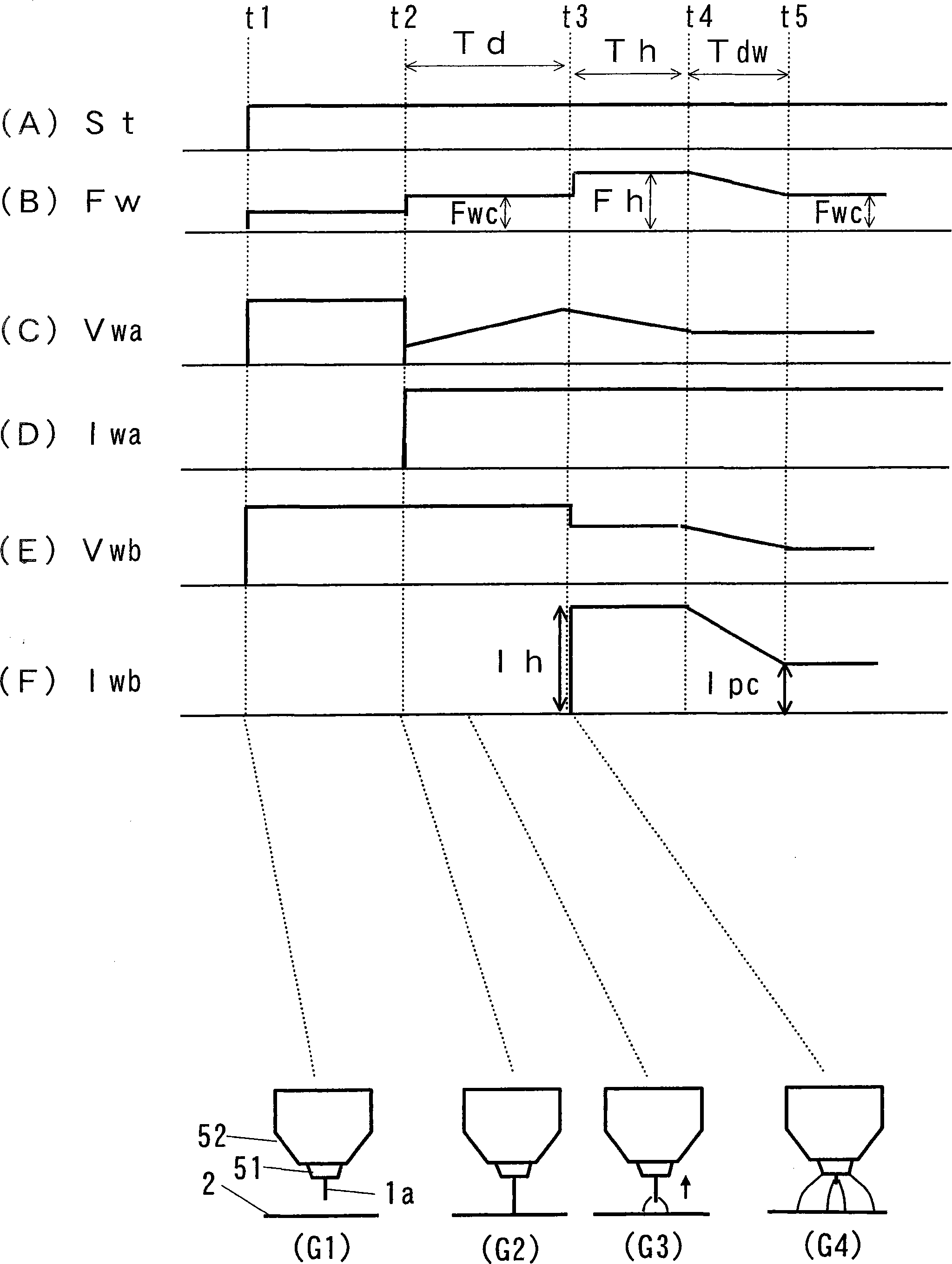
[0048] The second embodiment of the present invention differs from the first embodiment in the method of generating a melting electrode arc. That is, in the first embodiment, as in the period from time t2 to time t4 in Fig. (2), the welding wire is moved back and the melting electrode arc is generated. On the other hand, in the second embodiment, the arc is generated by advancing and feeding the welding wire in the same manner as the normal arc starting method in the metal electrode arc welding. Next, an arc start control method for two-electrode arc welding according to the second embodiment will be described.

[0049] The welding apparatus for implementing the arc start control method of two-electrode arc welding according to the second embodiment is the same as the above-mentioned figure 1 Same. However, the program control of the melting electrode arc welding power source PSM and the non-melting electrode arc welding power source PSP is different from that of the first ...


PUM


Abstract

PROBLEM TO BE SOLVED: To optimize penetration and a bead shape of an arc start part in two-electrode arc welding. SOLUTION: In a method for controlling arc start for two-electrode arc welding performing arc welding using a welding torch WT equipped with a consumable electrode 1a and a non-consumable electrode 1b, a consumable electrode arc 3a is generated between the consumable electrode 1a and a base material 2. Then, the consumable electrode 1a is fed at a normal feeding speed, a non-consumable electrode arc 3b is generated between the non-consumable electrode 1b and the base material 2. Thereafter, during a preheating period, a preheating current having a larger value than a normal current value is made to flow to the non-consumable electrode arc 3b, a feeding speed is switched to a preheating feeding speed that is faster than the normal feeding speed in accordance with the preheating current value. Upon completion of the preheating period, the feeding speed is switched to the normal feeding speed and, simultaneously, the current value for energizing the non-consumable electrode arc 3b is switched to the normal current value and made to shift to the normal welding state. COPYRIGHT: (C)2010,JPO&INPIT

Description

technical field [0001] The invention relates to an arc starting control method for double-electrode arc welding. A welding torch (the welding torch has a melting electrode and a non-melting electrode, and these electrodes are arranged in a protective gas nozzle) is used to generate a melting electrode arc and a non-melting electrode arc. In arc welding, it transitions smoothly to a stable welding state and forms a good weld bead. Background technique [0002] Figure 4 An example of a two-electrode arc welding device is shown. In this figure, the melting electrode arc is a MIG (Metal Inert Gas) arc, and the non-melting electrode arc is a plasma arc. This welding apparatus includes a welding torch WT surrounded by a dotted line, a melting electrode arc welding power source (MIG arc welding power source) PSM, and a non-melting electrode arc welding power source (plasma arc welding power source) PSP. The welding torch WT has a structure in which a plasma nozzle 51 , a plasma ...

Claims


Application Information

Patent Timeline
Patent Type & Authority Patents(China)
IPC IPC(8): B23K9/067B23K9/16
Inventor 小野贡平上山智之
Owner DAIHEN CORP
Why Eureka
Try Eureka