Tyre dismounting machine

A tire changer and rubber tire technology, which is applied in tire installation, tire parts, transportation and packaging, etc. It can solve the problem of uneven force on rubber tires and rims, excessive instantaneous impact force, and complex structure of claw tools and other problems, to achieve the effects of good structural stress mode, reduced friction, and reliable structural stability

Inactive Publication Date: 2010-09-29
CHONGQING UNIVERSITY OF SCIENCE AND TECHNOLOGY
View PDF7 Cites 8 Cited by
  • Summary
  • Abstract
  • Description
  • Claims
  • Application Information

AI Technical Summary

Problems solved by technology

The rubber tire removal device of the above structure mainly has the following disadvantages: one, the wheel rim needs to be loaded into the rotating shaft manually, and the efficiency is low; When pulling out from the rim, the speed is slow and the time is long; 3. When the claw-shaped tool is pulling out the rubber tire, it is always in partial contact with the rubber tire, resulting in uneven stress on the rubber tire and the rim, and severe local wear

Method used


Image

  • Tyre dismounting machine
  • Tyre dismounting machine
  • Tyre dismounting machine

Examples


Embodiment Construction

[0045] The present invention will be described in further detail below in conjunction with the accompanying drawings and specific embodiments.

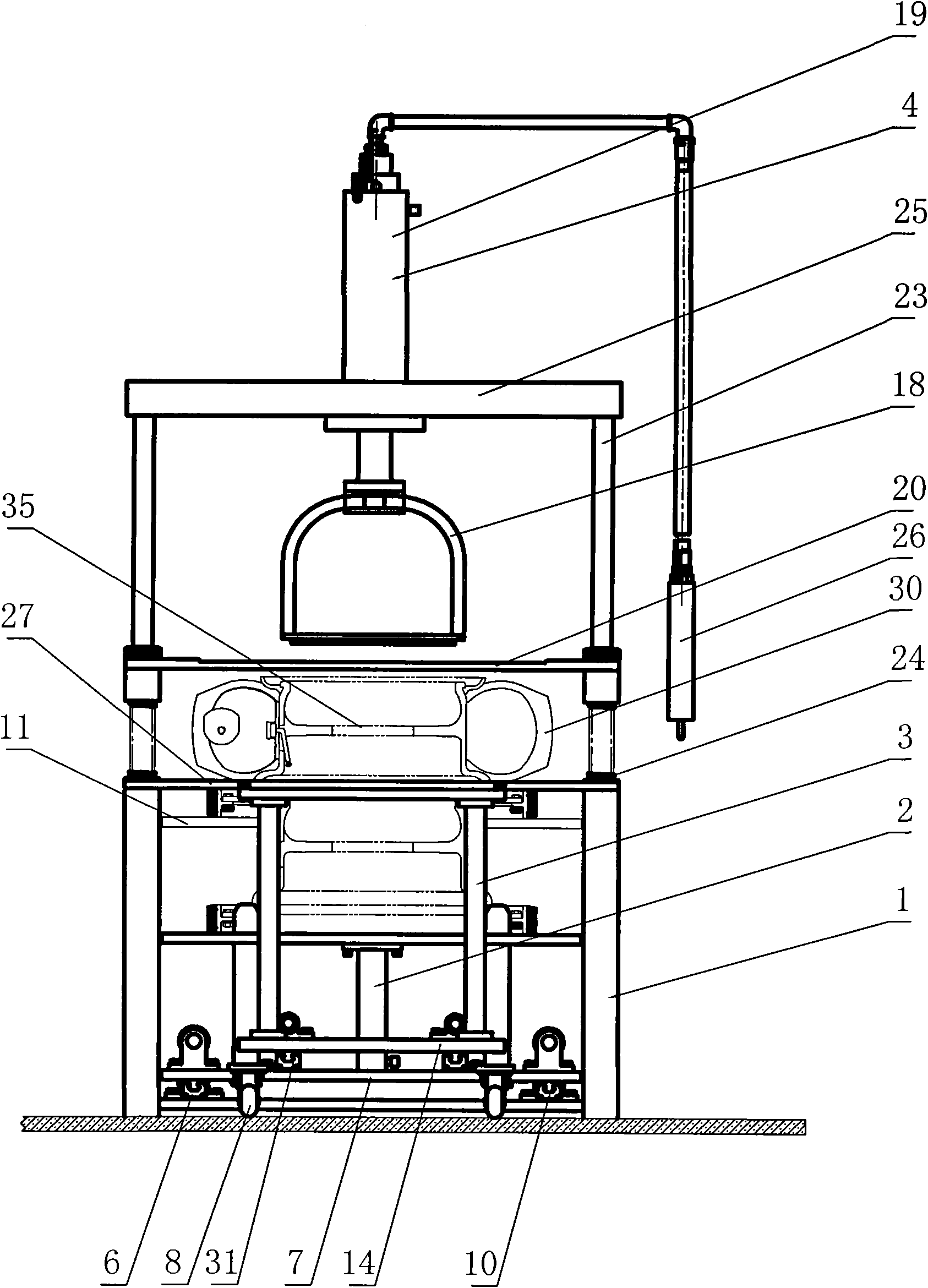
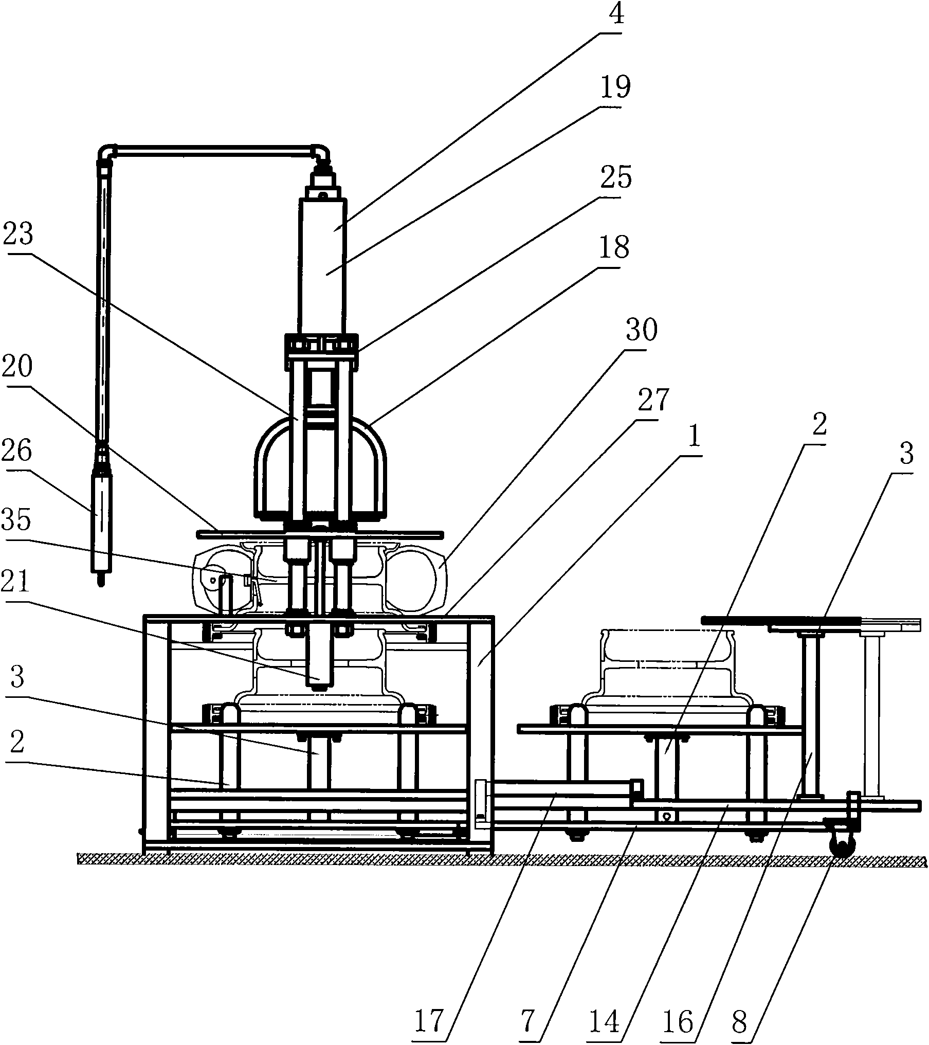
[0046] figure 1 It is the front view of the tire changer of the present invention, figure 2 It is the left view of the tire changer of the present invention, as shown in the figure: the tire changer includes a frame 1, a jacking device 2, a conveying device for sending the jacking device 2 into or out of the bottom of the frame 1, and a setting The brake block device 3 on the conveying device, the button operation display screen 26 with the control unit, and the wheel rim pressing device 4 and the rubber tire pressing device arranged on the top of the frame 1 .

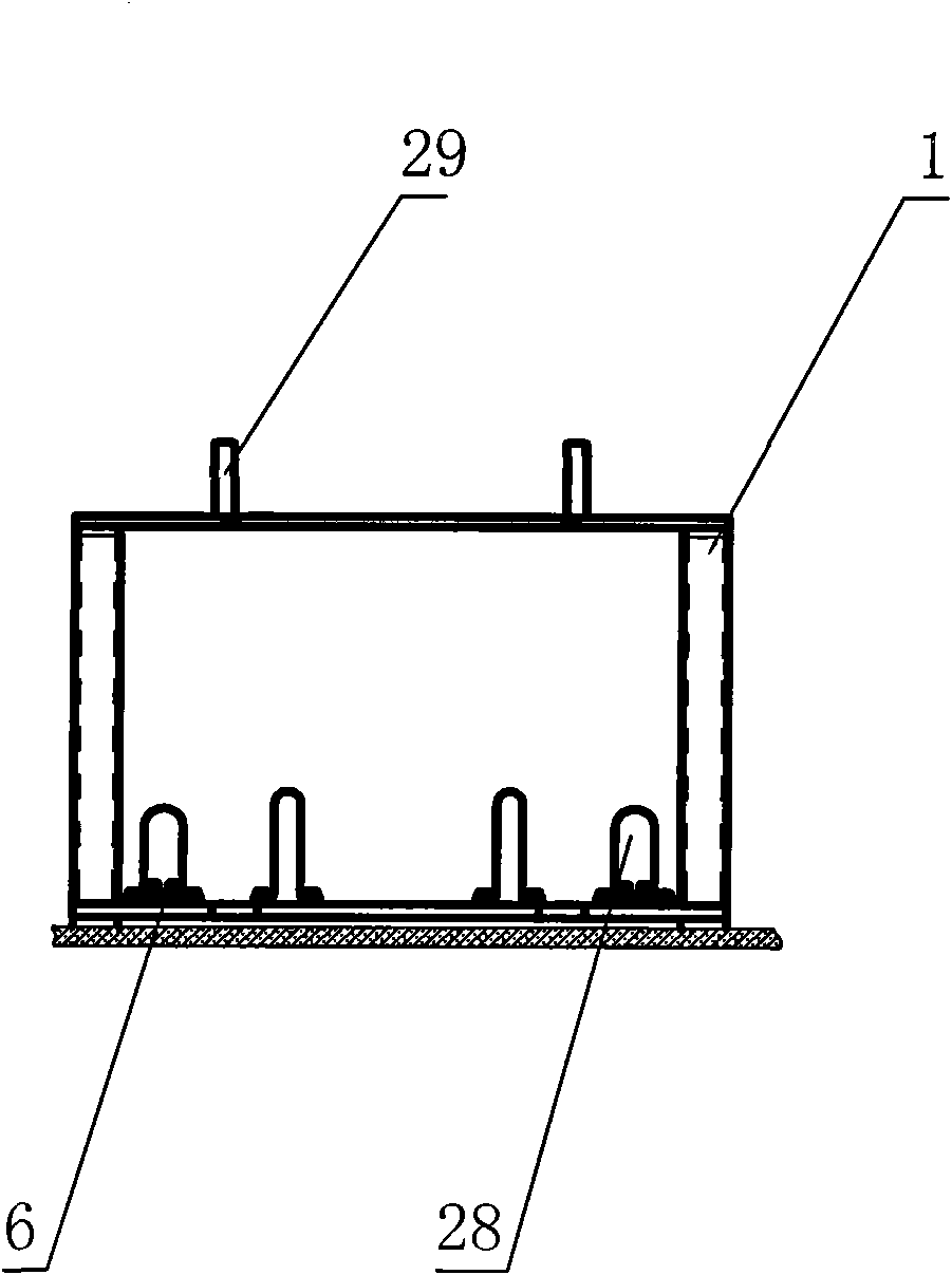
[0047] Rack 1 is a frame structure, such as image 3 , Figure 4 with Figure 5 As shown, one side of the frame 1 is the inlet and outlet of the conveying device, the top of the frame 1 is a worktable 27, and the worktable 27 is vertically provided with a through groove ...


PUM


Abstract

The invention discloses a tyre dismounting machine, comprising a rack, a jacking device, a conveyer device used for conveying the jacking device in and out the bottom of the rack, a brake block device arranged on the conveyer device and a rimmer pressing device arranged at the top of the rack. The rimmer of the invention is positioned by the jacking device and is conveyed to the bottom of the rimmer pressing device by the conveyer device, rubber tyre is placed at the top of the rack and is positioned by the brake block device, the entire process is realized by cylinder, efficiency is high, and positioning is accurate; the rubber tyre is horizontally placed at the top of the rack, pressure is vertically applied to the rimmer by the rimmer pressing device, and the tyre is pressed out from the rubber tyre, the dismounting manner in the prior art is changed, the rimmer pressing device adopts hydraulic driving, pressure is large, and the rimmer can be rapidly pressed out from the rubber tyre; and the rubber tyre is pressed on the rack, the rimmer pressing device adopts a rimmer clamping ring to be touched with the rimmer, entire stress is realized when in pressure application, stress is uniformly distributed, and friction between the rimmer and the rubber tyre is reduced.

Description

technical field [0001] The invention relates to a device for removing or installing tires, in particular to a tire changing machine. Background technique [0002] The rubber tire changer is a kind of equipment for installing or dismounting the rubber tire into the rim or automatically dismounting the rubber tire from the rim. [0003] There are generally two types of conventional rubber tire removal tools: bead separation tools and extraction tools, wherein the bead separation tool is used to be inserted between the rubber tire bead and the corresponding annular ring turnup to separate them ; The extraction tool, also known as a "jaw", has a curved end adapted to snap onto a rubber tire rim and remove it from the corresponding rim. Because the traditional disassembly tools are simple and require manual operation, the efficiency is low. At the same time, during disassembly, the rubber tire and rim are unevenly stressed, resulting in severe local wear. [0004] In order to o...

Claims


Application Information

Patent Timeline
Patent Type & Authority Applications(China)
IPC IPC(8): B60C25/138
Inventor 高月华张科廖亚宁
Owner CHONGQING UNIVERSITY OF SCIENCE AND TECHNOLOGY
Why Eureka
Try Eureka