Scraper conveyer

A technology of scraper conveyor and scraper chain, which is applied in the field of scraper conveyor, can solve problems such as the gap between the material chute and the drum, the accumulation of the tail of the scraper equipment, and the large amount of labor, so as to reduce the workload of workers and reduce the Effect of cleaning time and increasing service life

Inactive Publication Date: 2010-09-29
GUIZHOU CHITIANHUA PAPERS
View PDF0 Cites 8 Cited by
  • Summary
  • Abstract
  • Description
  • Claims
  • Application Information

AI Technical Summary

Problems solved by technology

[0002] Scraper conveyor is a common material conveying method in the field of material conveying. Currently, it is mostly used for solid material conveying. It has the advantages of solid structure, easy installation, and convenient forward and reverse rotation. It is easy to have the problem of returning materials, resulting in accumulation and blockage at the tail of the scraper equipment, making the equipment unable to operate safely and stably
Especially for scraper conveyors for solid-liquid separation and transportation, the problem of returning materials will be more serious, causing serious accumulation and blockage at the tail of the equipment, making it impossible to discharge the separated liquid, and it is difficult to achieve the effect of solid-liquid separation. There is a solution for manual cleaning at all times, which requires a large amount of labor
At the same time, the length of the existing material chute is fixed, and in order to adjust the tightness of the chain, the position of the drum will move backward, resulting in a gap between the material chute and the drum, resulting in excessive material accumulation

Method used


Image

  • Scraper conveyer
  • Scraper conveyer

Examples


Embodiment 1

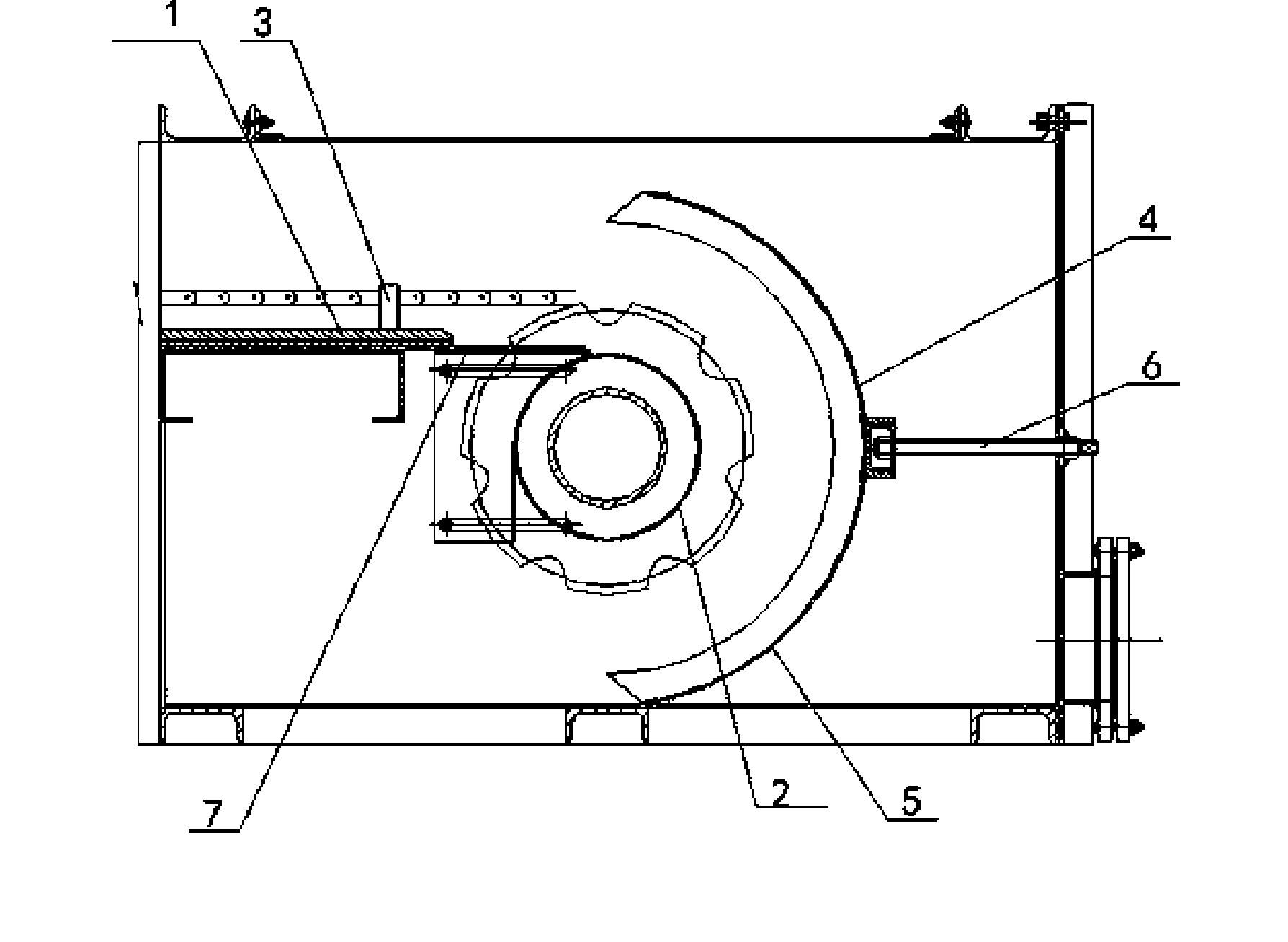
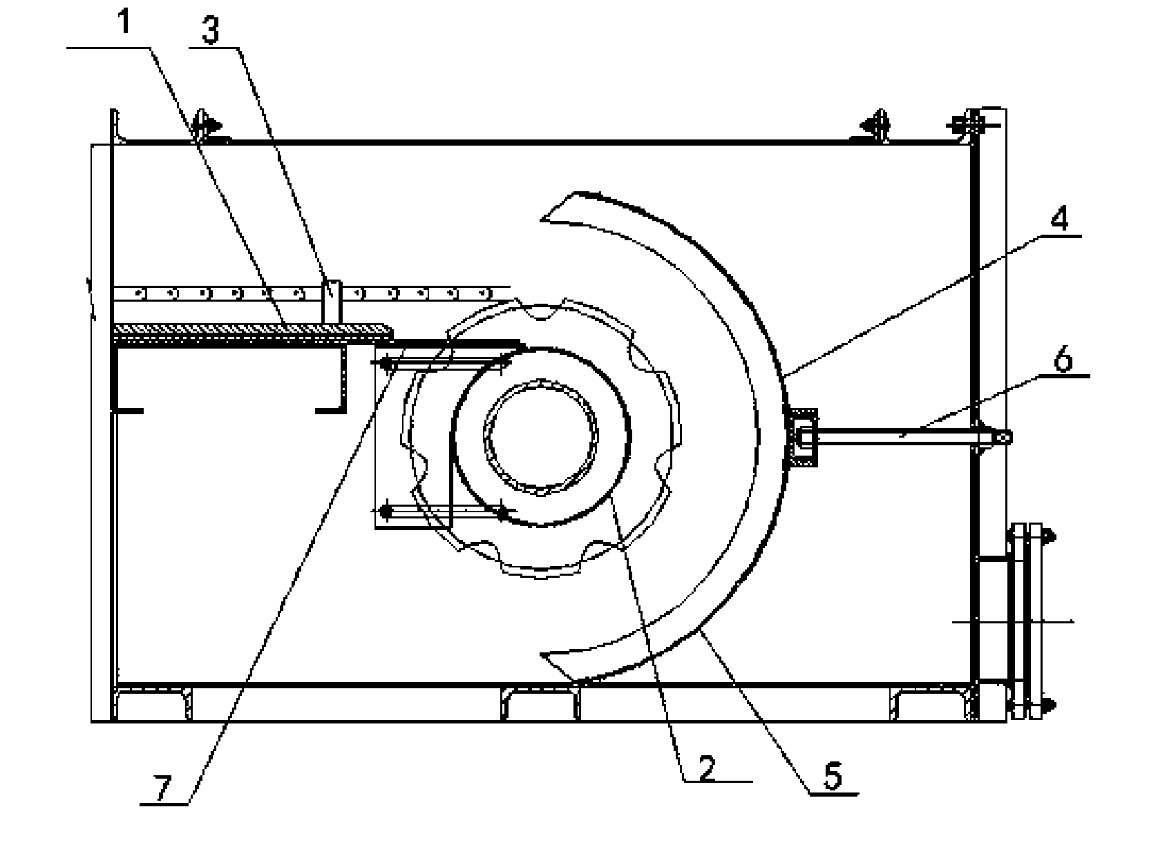
[0012] Embodiment 1: as figure 1 As shown, the material chute 1 is fixed on the frame, and a drum 2 is arranged at both ends of the material chute 1, and the two ends of the drum 2 are also connected with the frame, and a matching scraper is arranged at both ends of the drum 2 Chain, a scraper 3 is installed at intervals on the scraper chain, and an arc baffle 4 is installed at one end of the drum 2 at the tail end. The width of the arc baffle 4 is equal to the width of the material chute 2 and less than the width of the frame; There is a water leakage hole 5 on the shaped baffle plate 4, and the preferred position of the water leakage hole 5 is the lower half of the arc baffle plate 4, and a mobile adjustment device 6 is installed in the middle of the arc baffle plate 4, and the mobile adjustment device 6 adopts a simple structure. Bolt adjustment assembly. In this way, when the scraper conveyor is working, the material brought back to the tail by the scraper 3 will roll bac...


PUM


Abstract

The invention discloses a scraper conveyer which comprises a material chute (1); both ends of the material chute (1) are provided with drums (2); both ends of each drum (2) are provided with scraper chains in a matching way; scrapers (3) are arranged on the scraper chains at interval sections; and one end of each drum (2) is provided with an arc-shaped baffle (4). One arc-shaped baffle is arranged on one end of each drum, so materials which are taken by the scrapers to the tail part in a return process are scrolled back to the upper end of the material chute along the arc-shaped baffles and taken away by the scrapers, so that no material is piled and blocked at the tail part of the equipment; and the arc-shaped baffles are provided with water leaking poles, so that the liquid flows out from the water leaking holes when the solid and liquid of the materials are separated and the solid is taken away by the scrapers, is separation efficiency is greatly improved, and a liquid runner is not blocked.

Description

technical field [0001] The invention relates to a scraper conveyor, which belongs to the technical field of material transmission. Background technique [0002] Scraper conveyor is a common material conveying method in the field of material conveying. Currently, it is mostly used for solid material conveying. It has the advantages of solid structure, easy installation, and convenient forward and reverse rotation. It is easy to have the problem of returning materials, resulting in accumulation and blockage at the tail of the scraper equipment, making the equipment unable to operate safely and stably. Especially for scraper conveyors for solid-liquid separation and transportation, the problem of returning materials will be more serious, causing serious accumulation and blockage at the tail of the equipment, making it impossible to discharge the separated liquid, and it is difficult to achieve the effect of solid-liquid separation. There is a solution for manual cleaning at al...

Claims


Application Information

Patent Timeline
Patent Type & Authority Applications(China)
IPC IPC(8): B65G19/04B65G19/18B65G19/28
Inventor 刘荣辉李友谊郑东义张艺
Owner GUIZHOU CHITIANHUA PAPERS
Why Eureka
Try Eureka