
Arrangement method based on dynamic balance unit technology in hot water heating system

A dynamic balance, hot water heating technology, applied in hot water central heating systems, heating systems, heating methods, etc., can solve problems that have not received corresponding attention, thermal and hydraulic system imbalance, and affect the quality of building heating

Inactive Publication Date: 2010-09-29
XINJIANG FUDE ENERGY SAVING ENG +1
View PDF1 Cites 25 Cited by
  • Summary
  • Abstract
  • Description
  • Claims
  • Application Information

AI Technical Summary

Problems solved by technology

However, at present, while promoting heat metering, the application of matching new technologies and methods of heating networks has not received corresponding attention; the heating network of new buildings is still designed and constructed according to the principle of constant flow, and the user's adjustment behavior at any time will cause the entire The fluctuation of the heating network causes the imbalance of the thermal and hydraulic systems, thus affecting the heating quality of the building

Method used


Image

  • Arrangement method based on dynamic balance unit technology in hot water heating system
  • Arrangement method based on dynamic balance unit technology in hot water heating system
  • Arrangement method based on dynamic balance unit technology in hot water heating system

Examples


Embodiment Construction

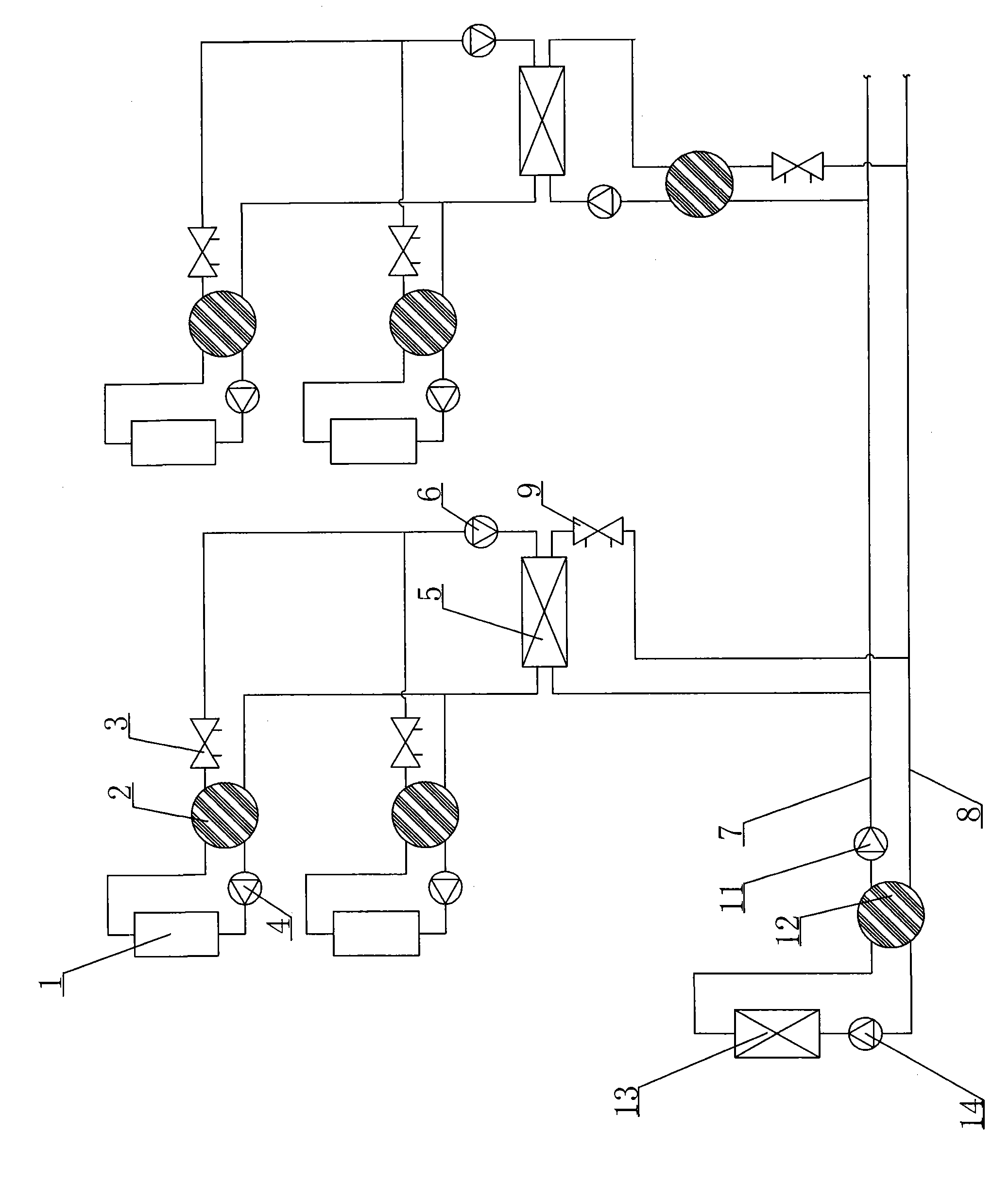
[0011] A layout method based on dynamic balance unit technology in hot water heating system, such as figure 1 As shown, including a dynamic balance unit, the return water line 8 of the total heating network is connected to the inlet end of the boiler 13 through the total heating network circulation pump 14, and the outlet end of the boiler 13 is connected with the water supply line 7 of the total heating network, so that the total The return water pipeline 8 of the heating pipe network is connected to the inlet end of the boiler 13 through the return water overflow device of the first-level dynamic balance unit 12 and the circulation pump 14 of the total heating network, and the water supply pipeline 7 is passed through the inlet port of the first-level dynamic balance unit 12. The water overcurrent device and the total water inlet circulation pump 11 are connected to the water inlet of the input end of the heat exchanger 5, and then the return water line 8 of the total heating...


PUM


Abstract

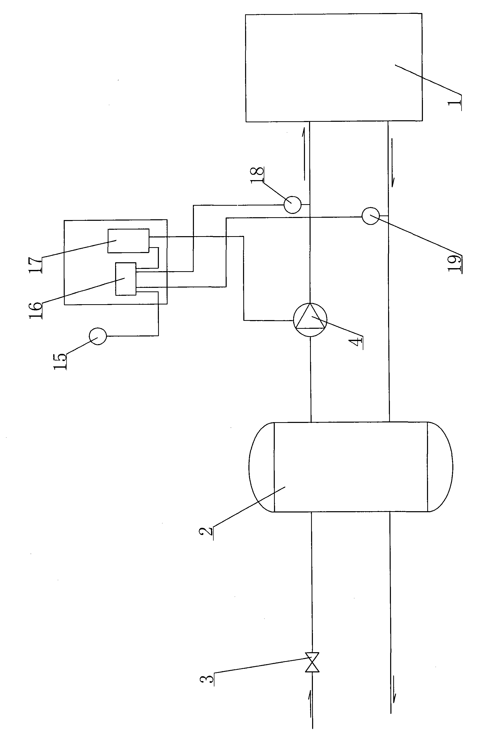
The invention discloses an arrangement method based on the dynamic balance unit technology in a hot water heating system. In the method, a backwater pipeline is connected to a boiler inlet end through a general heat network circulating pump; a boiler outlet end is connected by a water supply pipeline; the backwater pipeline of a general heating pipe network is connected to the boiler inlet end through a primary dynamic balance unit backwater over-current device and the general heat network circulating pump; the water supply pipeline is communicated with a water inlet of the input end of a heat exchanger through the primary dynamic balance unit backwater over-current device and a general water inlet circulating pump; and the backwater pipeline of the total heating pipe network is communicated with a water outlet of the input end of the heat exchanger through a general-grade balance valve, wherein a water outlet and a water inlet of the output end of the heat exchanger are respectively connected with a water supply pipeline and a backwater pipeline of a branched heating pipeline, a circulating pump of the output end is communicated in series to a backwater pipeline of the branched heating pipeline, an outlet end of a user heating pipe network is connected with the backwater pipeline of the branched heating pipe network through a secondary dynamic balance unit water backwater over-current device and a secondary balance valve, and a branched heating pipe network water inlet pipeline is connected with a user heating pipe network inlet end through a secondary dynamic balance unit water inlet over-current device and a circulating pump of the input end. The method reduces the flow of heat network dry pipe, reduces the designed pipe diameter of the dry pipe and saves the construction cost of the heat network.

Description

technical field [0001] The invention relates to a method for arranging a dynamic balance unit in an existing heating pipe network system, in particular to an arrangement method based on the technology of a dynamic balance unit in a hot water heating system. Background technique [0002] In the traditional heating system, it is customary to set the secondary circulating water pump at the heat exchange station (heat exchanger), and its function is not only the circulating water pump of the heat exchange station (heat exchanger) heating network, but also the circulating water pump of the secondary heating network. In the design and selection of circulating water pumps, the circulation flow is equal to the system design flow, and the lift is equal to the sum of heat source resistance loss, heat network resistance loss and end heat user's resource pressure head. The type selection of the water pump works in a large-flow operation mode, and a considerable surplus flow is also give...

Claims


Application Information

Patent Timeline
IPC IPC(8): F24D3/10F24D3/02F24D19/10
Inventor 何伟
Owner XINJIANG FUDE ENERGY SAVING ENG
Learn More