Single-brush commutator

A commutator and commutator piece technology, applied in the direction of DC commutators, electrical components, electromechanical devices, etc., can solve the problems of uncertain starting torque direction, high speed, lack of practical application value, etc., to achieve no short circuit, Improved life and simple and reliable structure

Inactive Publication Date: 2010-09-29
冯鲁民
View PDF0 Cites 0 Cited by
  • Summary
  • Abstract
  • Description
  • Claims
  • Application Information

AI Technical Summary

Problems solved by technology

Usually because the brush commutator of this kind of motor has no starting torque at a specific position of the rotor, the direction of the starting torque is uncertain, and there is a

Method used


Image

  • Single-brush commutator
  • Single-brush commutator
  • Single-brush commutator

Examples


Example Embodiment

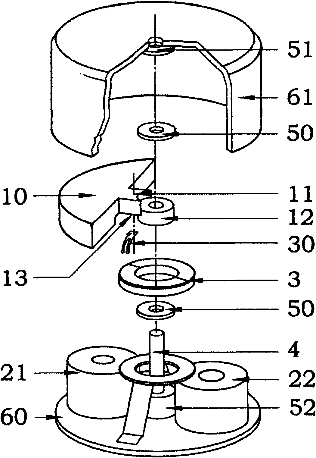
[0026] figure 1 Shown is a structural diagram of a DC miniature vibration motor according to the first preferred embodiment of the present invention. The motor takes the form of in-line two-phase coils of the stator without iron core and eccentric permanent magnets of the two poles of the rotor.

[0027] The permanent magnet eccentric rotor (1) is located on the axial side of the stator coils 1 (21) and 2 (22), and is supported by the lower shaft seat (52) so that the rotor (1) and the stator coil (2) are on the axis To maintain a very small magnetic air gap. The stator coils 1 (21) and 2 (22) are hollow, the axes of the two coils (21) and (22) are parallel to the fixed axis, and the line between the axis of the two stator coils is orthogonal to the axis of the fixed shaft (4) . The stator coil 1 (21) and the stator coil 2 (22) are bonded and fixed on the motor base plate (60). One end of the fixed shaft (4) is fixed on the lower shaft seat (52) of the motor bottom plate (60),...


PUM


Abstract

The invention relates to a single-brush commutator used by a drive winding of a 2/2 pole permanent magnet direct current motor. The single-brush commutator is totally provided with four commutating pieces; the four commutating pieces are divided into two groups, each group comprises two commutating pieces, and each commutating piece and the commutating piece in the same group are placed on the circumference in an opposite way. One group of commutating pieces is mutually connected, and the other group is not connected with any other commutating pieces. An included angle of the front edge and the rear edge of one group of two mutually connected commutating pieces is equal to a supplementary angle of an included angle of two magnetic poles of a rotor or is equal to an effective action angular distance of a winding of a set stator and a magnetic pole of the rotor; and an included angle of the front edge and the rear edge of the other group of two commutating pieces is equal to the included angle of two magnetic poles of the rotor.

Description

technical field [0001] The invention relates to the structure of a permanent magnet rotor DC motor under an asymmetrical magnetic field, in particular to a flat miniature vibration motor. Background technique [0002] At present, there are two types of flat micro-vibration motor structures, one with a commutator and the other without a commutator, relying on an external commutation circuit to commutate the coil. [0003] Micro vibration motors are used in mobile phones or other personal portable electronic information products, and generally use batteries as power sources. Therefore, micro motors are required to consume less power on the one hand, small in size, and light in weight. On the other hand, they must meet the application purpose: Sufficient vibration force. At present, the vibration strength of the flat vibration motor with the coil as the rotor has basically reached the limit, and the complicated manufacturing process also makes it difficult to reduce the cost o...

Claims


Application Information

Patent Timeline
IPC IPC(8): H02K13/00H02K23/04
Inventor 冯鲁民
Owner 冯鲁民
Why Eureka
Try Eureka