Dynamic fountain ornament
A technology of fountains and ornaments, applied in the direction of decorative arts, spraying devices, liquid spraying devices, etc., to achieve the effect of increasing performance
- Summary
- Abstract
- Description
- Claims
- Application Information
AI Technical Summary
Problems solved by technology
Method used
Image
Examples
Embodiment 1
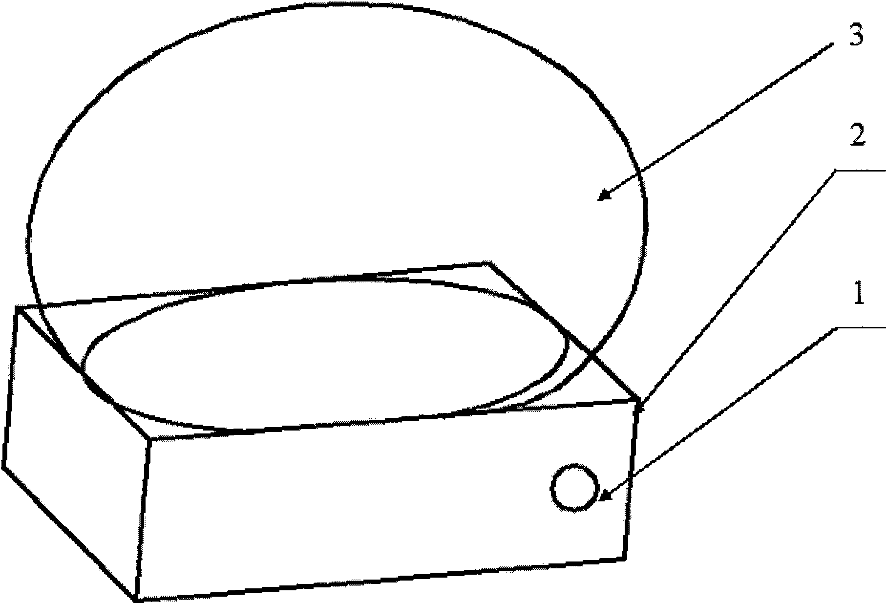
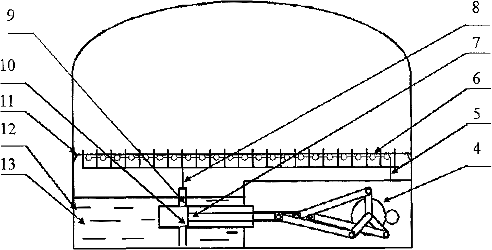
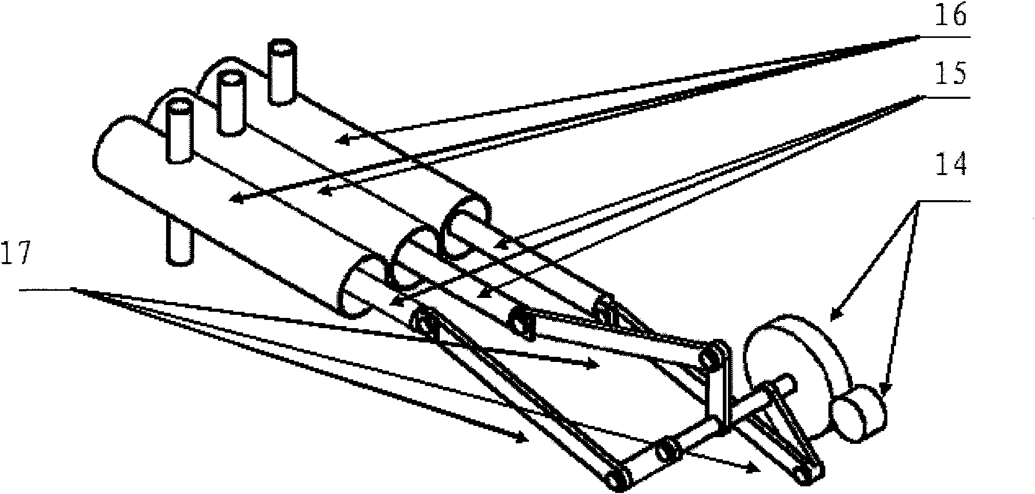
[0024] Embodiment one: see figure 1 , figure 2 , image 3 with Figure 4 , 1, this dynamic fountain ornament, it comprises: shell 3, base 2 and power switch 1, described shell 3 is glass shell, there is partition between shell 3 and base 2, there are n rows of parallel Arranged fountain tubes 8 (n is a natural number except zero), and there is a backflow tank around the partition; 2. A power supply 20 is installed in the inner cavity of the base 2 below the partition to connect a motor 18, and the motor 18 is connected to A gear reducer 14 drives a crank-piston mechanism 17, and the crank-piston mechanism 17 links n piston rods 15 to drive the pistons 7 in n suction cylinders 16, and each suction cylinder 16 has two check valves 9, 10 , one of the one-way valves 10 is connected to the pool box 12 formed at the lower part of the base 2, and the one-way valve 10 can only enter water from the pool box 12 to the system 16, and the other one-way valve 9 is connected to the foun...
Embodiment 2
[0025] Embodiment two: see Figure 1 to Figure 4 , the present embodiment is basically the same as Embodiment 1, and the special features are as follows: the structure of the crank-piston mechanism 17 is: a rotating shaft is driven by a motor 18 through a gear reducer 14, and n cranks are connected on the rotating shaft to drive n Root piston rod 15. The said shell 2 is an oval spherical glass shell. Said every row of fountain tubes 8 has LED multicolored lamp tubes 6 beside them. The base 2 is provided with a music device 19 . The power supply 20 is connected to the music device 19 and the motor 18 via the power switch 1 .
Embodiment 3
[0026] Embodiment 3: The description of this dynamic fountain ornament is as follows: see figure 1 :exist figure 1 The appearance of the entire invention can be seen in . There are shell 3, base 2 and power switch 1. see figure 2 : figure 2 It is a perspective front view of the internal structure. When the transmission mechanism 4 is activated, one of the three pistons moves to the right, n=3. At this time, the lower one-way valve 10 in the suction cylinder is opened to suck the water in the pool box 12 13 into the suction cylinder. When the piston moved to the left, the lower one-way valve 10 was closed, and the upper one-way valve 9 was opened. A jet of water is sprayed out. LED multicolored lamp 6 links to each other with lead 5, and when spraying, under the illumination of LED multicolored lamp 6, whole scenery is very beautiful.
[0027] see image 3 : image 3 is a perspective view of the transmission mechanism 4 . When starting, the small gear in the gear se...
PUM
 Abstract
Description
Claims
Application Information
 - R&D
- Intellectual Property
- Life Sciences
- Materials
- Tech Scout
- Unparalleled Data Quality
- Higher Quality Content
- 60% Fewer Hallucinations
Browse by: Latest US Patents, China's latest patents, Technical Efficacy Thesaurus, Application Domain, Technology Topic, Popular Technical Reports.
© 2025 PatSnap. All rights reserved.Legal|Privacy policy|Modern Slavery Act Transparency Statement|Sitemap|About US| Contact US: help@patsnap.com


