Chain-type boosting inlet roller machine for oscillating bar conveyer

A conveyor and roller bed technology, applied in conveyors, conveyor objects, transportation and packaging, etc., can solve the problems of reduced friction between the bottom surface of the skid and the surface of the rollers, occupied takt time, dripping, etc., saving waiting time, reducing frictional resistance, small impact and vibration effects

Active Publication Date: 2010-10-06
AUTOMOTIVE ENG CORP +1
View PDF6 Cites 6 Cited by
  • Summary
  • Abstract
  • Description
  • Claims
  • Application Information

AI Technical Summary

Problems solved by technology

At present, the entrance roller bed using a pneumatic booster mechanism is widely used to complete the transition of workpieces and skids from the skid conveying system to the pendulum conveying system, but there are still some deficiencies in practical applications: 1. Pendulum conveying Machine entrance handover requires high precision and high reliability
Since the bottom surface of the sled body that reaches the entrance tumbling bed is wet, and the liquid carried by the sled body and the workpiece will inevitably drip onto the rollers of the tumbling bed, the friction between the bottom surface of the sled body and the surface of the rollers is reduced, causing the sled body to roll The bed slipped, causing the transfer of the workpiece to the pendulum to fail
[0003] 2. When the pneumatic booster mechanism pushes the sled close to the front positioner, it will generate a large impact, vibration and noise
Occupying part of the takt time of the entrance roller bed, the result can only meet the production requirements of the automobile factory at 40JPH, and cannot meet the production requirements of speed-up and high-efficiency

Method used


Image

  • Chain-type boosting inlet roller machine for oscillating bar conveyer
  • Chain-type boosting inlet roller machine for oscillating bar conveyer
  • Chain-type boosting inlet roller machine for oscillating bar conveyer

Examples


Embodiment approach

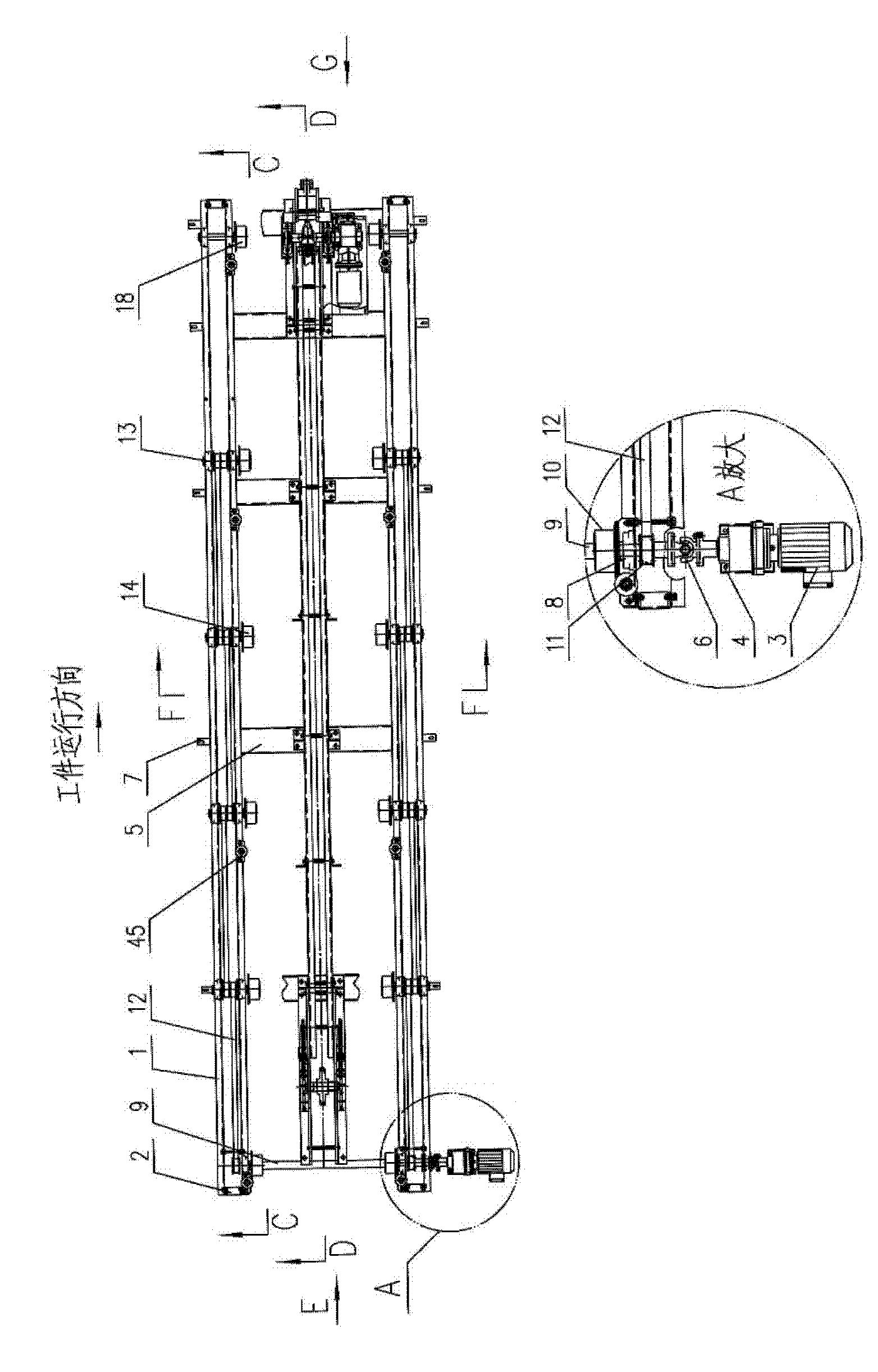
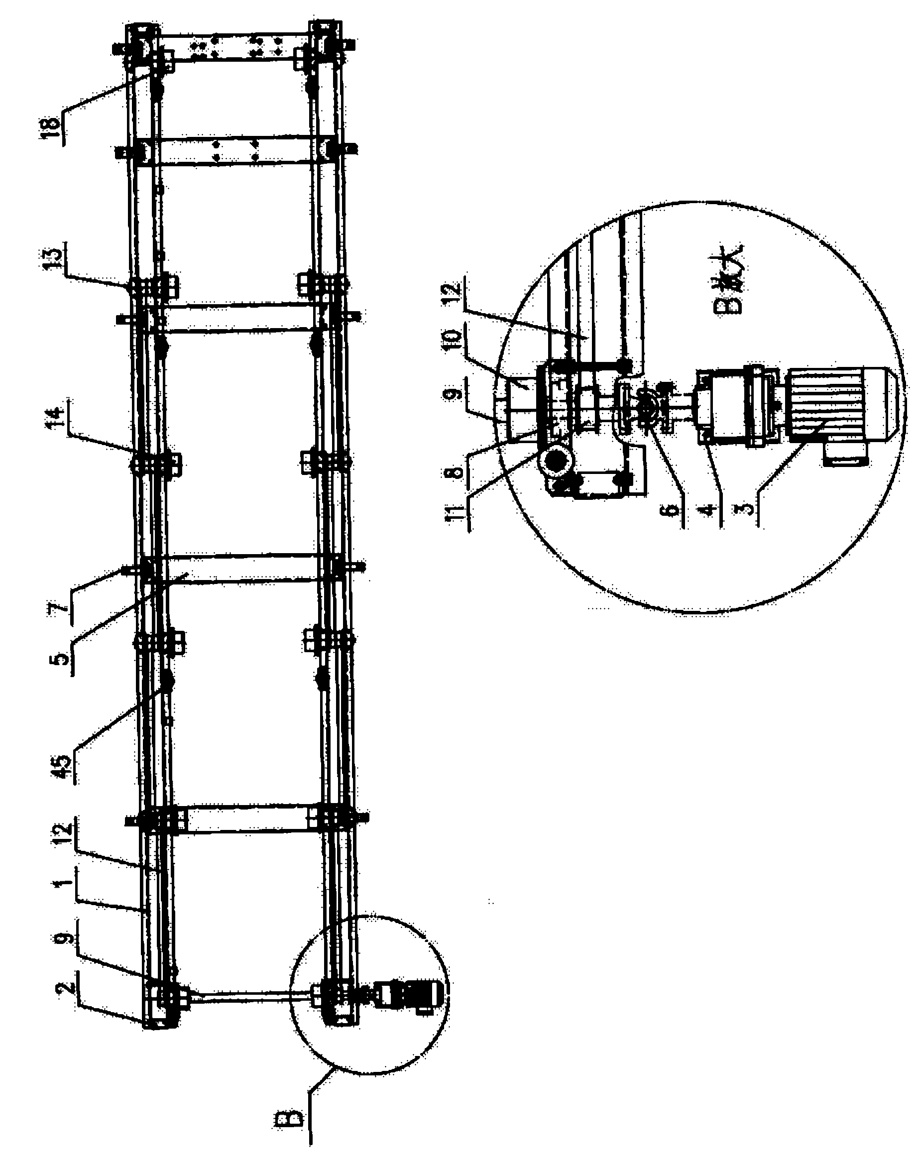
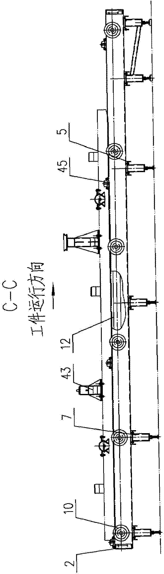
[0010] DETAILED DESCRIPTION OF THE PREFERRED EMBODIMENTS: In order to further understand the content, characteristics and effects of the present invention, the following embodiments are exemplified and described in detail with the accompanying drawings as follows, please refer to Figure 1-Figure 9 .

[0011] The chain-type booster inlet roller bed used for the swing bar conveyor includes a roller bed, a booster mechanism and a positioning mechanism, and is characterized in that: figure 1 , figure 2 Shown: The present invention consists of a roller bed with a separate assembly structure, a chain booster mechanism with an assembled frame structure, and a pneumatic positioning mechanism.

[0012] like Figure 3-Figure 5 , Figure 9 Shown: the tumbler with separate assembly structure is mainly composed of tumbler U-shaped plate 1, end plate 2, tumbler gear motor 3, motor bracket 4, fixed leg beam 5, universal joint 6, fixed leg 7. A belt seat bearing 8, composed of long roll...


PUM


Abstract

The invention relates to a chain-type boosting inlet roller machine for an oscillating bar conveyer. The roller machine consists of a frame, a speed reducing motor, a universal joint, and a long roller component, a short roller component and a free roller component which are used for supporting and conveying a runner, wherein a roller is supported in a plummer block on the frame; an adjustable support leg is fixed to the lower part of the frame; a chain-type boosting mechanism consists of a tensioning section, a driving section and a middle section which are linked with one another through a chain; the chain is provided with a push head and runs in a groove track of each section; a sledge body which bears a workpiece is supported on the roller; the chain is driven by the speed reducing motor in the driving section; the push head pushes a sledge body cross beam to move forward and be jointed with the oscillating bar, so that the roller machine starts running. Since the chain runs stably at a low speed without impact, the jointing reliability and stability of the sledge body and the oscillating bar are high. An oscillating arm of a positioning mechanism is driven by a cylinder so as to block and position the sledge body. The roller machine is characterized by full chain transmission process, no sliding of the sledge body in the roller machine, low running speed, stability, little impact and shock, high reliability and capacity of more than or equal to 60 JPH.

Description

technical field [0001] The invention belongs to the technical field of material conveying, and particularly relates to a chain-type booster inlet roller bed used for a pendulum conveyor. Background technique [0002] As we all know, the entrance roller bed is an indispensable basic conveying equipment in a modern automobile factory with a pendulum conveyor system. At present, the inlet roller bed using a pneumatic booster mechanism is widely used to complete the transition of the workpiece and the sled from the skid conveying system to the pendulum conveying system, but there are still some deficiencies in practical applications: 1. Pendulum conveying The machine entrance handover requires high precision and high reliability. The transition from the workpiece and the sled to the pendulum rod is transported by the roller bed half of the time, and by the pneumatic booster mechanism for half of the time. Since the bottom surface of the sled body that reaches the inlet roller ...

Claims


Application Information

Patent Timeline
Patent Type & Authority Applications(China)
IPC IPC(8): B65G47/52B65G19/02B65G19/18B65G19/24B65G23/44
Inventor 戈北京牛利超张延虎王新峰赵亮
Owner AUTOMOTIVE ENG CORP
Why Eureka
Try Eureka