Sequencing batch photocatalytic reactor

A photocatalytic reaction and sequencing batch technology, which is applied in chemical instruments and methods, light water/sewage treatment, magnetic separation, etc. Effect

Inactive Publication Date: 2010-10-06
HARBIN ENG UNIV
View PDF3 Cites 9 Cited by
  • Summary
  • Abstract
  • Description
  • Claims
  • Application Information

AI Technical Summary

Problems solved by technology

[0007] By searching many documents, no reaction device similar to the present invention is found

Method used


Image

  • Sequencing batch photocatalytic reactor
  • Sequencing batch photocatalytic reactor
  • Sequencing batch photocatalytic reactor

Examples


Embodiment Construction

[0021] The present invention is described in more detail below in conjunction with accompanying drawing example:

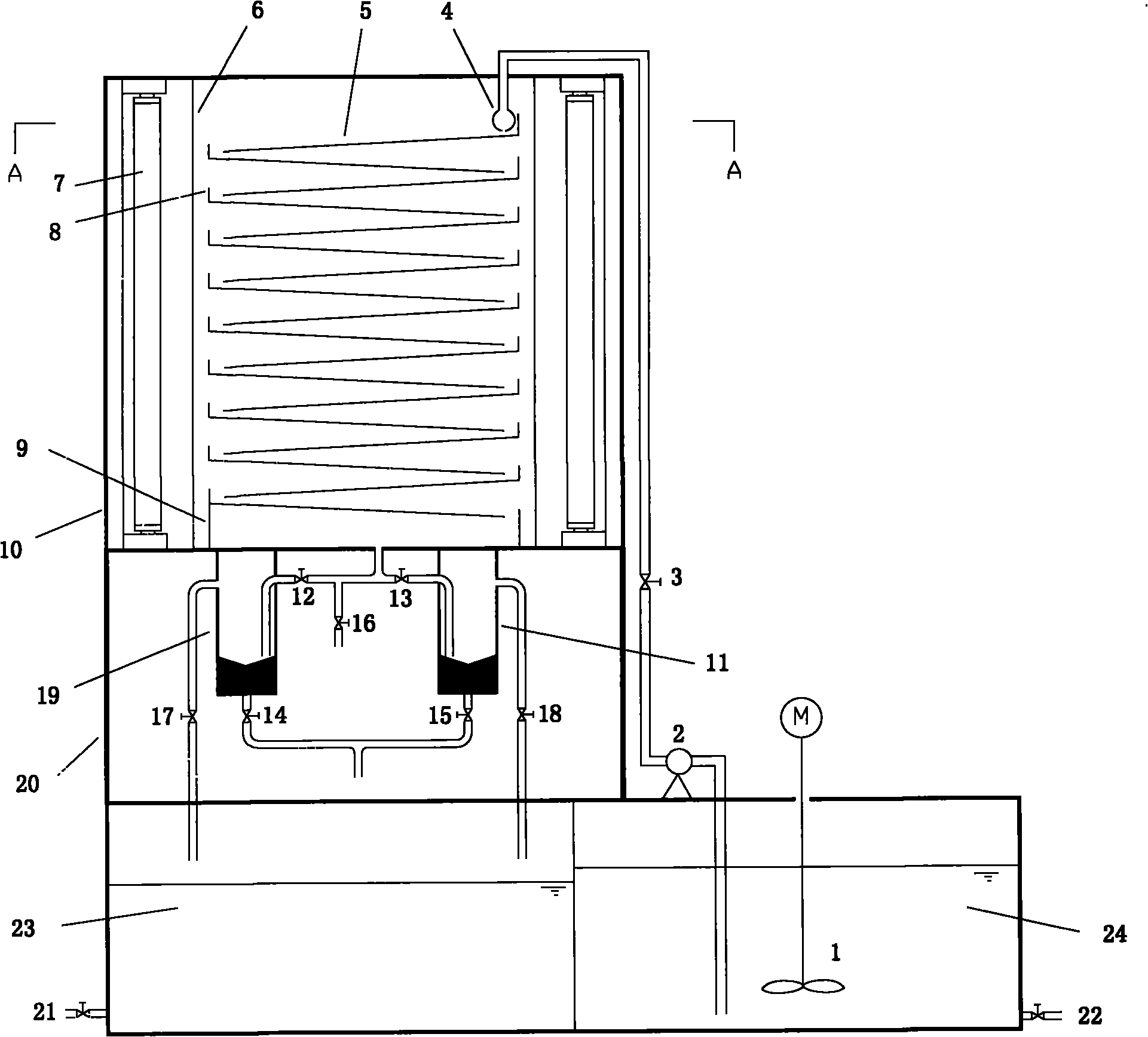
[0022] figure 1 The meanings of the labels in are: 1- agitator; 2- water supply pump; 3- flow regulating valve; 4- water distributor; 5- inclined plate; Water receiving tank; 10-shell; 11-No. 2 separator; 12-No. 1 separator water inlet valve; 13-No. 2 separator water inlet valve; 14-No. 1 separator emptying valve; 15-No. 2 separator Empty valve; 16-sampling valve; 17-1 separator overflow valve; 18-2 separator overflow valve; 19-1 separator; 20-support column; 21-clean water tank drain valve; 22- Sewage tank drain valve; 23-clean water tank; 24-sewage tank.

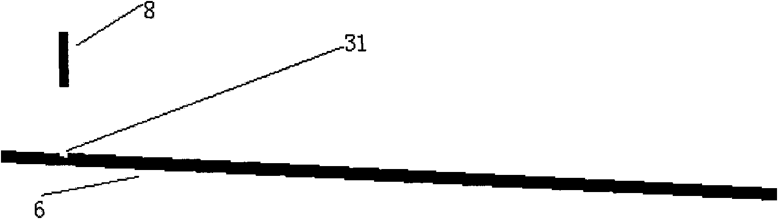
[0023] figure 2 The meanings of each label in are: 5-slope; 8-baffle; 31-groove.

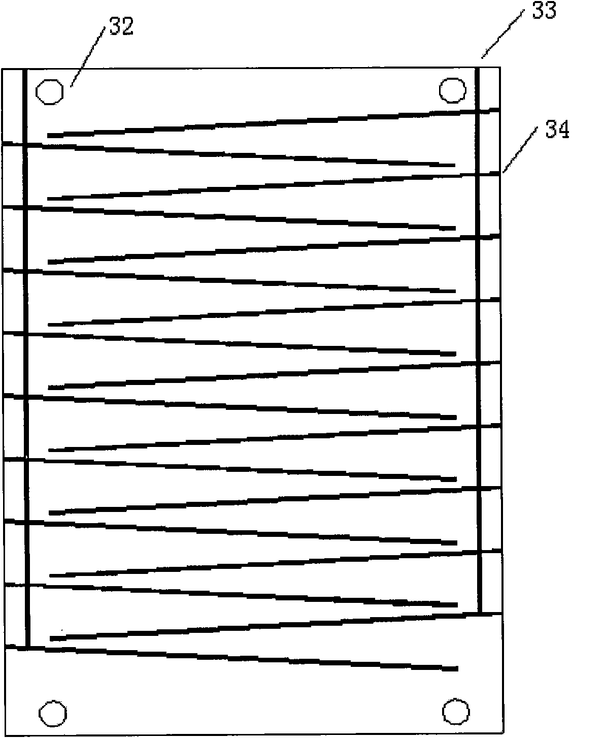
[0024] image 3 The meanings of each label in : 32-bolt hole; 33-longitudinal groove; 34-oblique groove.

[0025] Figure 4 The meanings of the labels in are: 7-light source; 6-partition; 8-baffle; 4-water distributor; 3...


PUM

PropertyMeasurementUnit
heightaaaaaaaaaa
thicknessaaaaaaaaaa
widthaaaaaaaaaa

Abstract

The invention provides a sequencing batch photocatalytic reactor, which comprises a reaction section, a separation section, a separation section, a clean water tank and a sewage tank; the reaction section comprises a shell, an inclined plate section and light sources, wherein the inclined plate section is positioned in the middle of the shell, the light sources are positioned on both sides of the inclined plate section, the inclined plate section consists of upright plates, inclined plates and baffles, which are connected, a water distributor is arranged over the inclined plate on the upmost layer, and is connected with the sewage tank through a conduit, a control valve and a water supply pump, and a water-receiving tank is arranged under the inclined plate on the lowest layer; the separation section comprises separators, each separator comprises an upper water accumulator and a bottom soft magnet, the separators are connected with the water-receiving tank through conduits and valves, and each water accumulator is provided with an overflow tube and a discharge tube. The reactor operates by the way of sequencing batch; catalyst and pollutant can be uniformly mixed, so the contact effect is good; liquid is shaped like a film when flowing on the inclined plates of the reactor, so the effect of utilizing direct light and reflected light is good; and sampling inspection is convenient. Catalyst can be conveniently recovered; the catalyst load can be flexibly adjusted; and the operation is simple and flexible.

Description

technical field [0001] The invention relates to an experimental device, in particular to a photocatalytic reaction device. Background technique [0002] The research and development of semiconductor photocatalytic materials is a hot spot in the field of scientific research. At present, scholars at home and abroad have made many remarkable achievements, and have prepared magnetic photocatalysts with good utilization effects on visible light. However, the research and development and design of reaction devices are less, lagging far behind the speed of catalyst research and development, which seriously restricts the application of high-quality catalysts. [0003] The photocatalytic reaction device is the place for photocatalytic reaction. For the research on the device, the existing types at home and abroad mainly include: 1. Fluidized bed photocatalytic reactor; 2. Liquid film photocatalytic reactor; 3. Quartz tube type Photocatalytic reactor, 4, flat plate reactor, etc. The...

Claims


Application Information

Patent Timeline
Patent Type & Authority Applications(China)
IPC IPC(8): C02F1/30B03C1/00
Inventor 夏淑梅刘继明刘广民陈兆波
Owner HARBIN ENG UNIV
Why Eureka
Try Eureka