A fuel injector for internal combustion engines

A technology for fuel injectors and internal combustion engines, which is applied to fuel injection devices, machines/engines, charging systems, etc., can solve the problem that the total number of nozzle holes cannot be increased, and achieve the effect of improving spray quality and fuel combustion and optimizing spray quality.

Active Publication Date: 2015-06-24
WAERTSILAE SWITZERLAND
View PDF8 Cites 0 Cited by
  • Summary
  • Abstract
  • Description
  • Claims
  • Application Information

AI Technical Summary

Problems solved by technology

The problem with this solution is that the total number of nozzle holes arranged in the maximum angle cannot be increased without jeopardizing the strength of the side walls of the atomizer

Method used


Image

  • A fuel injector for internal combustion engines
  • A fuel injector for internal combustion engines
  • A fuel injector for internal combustion engines

Examples


Embodiment Construction

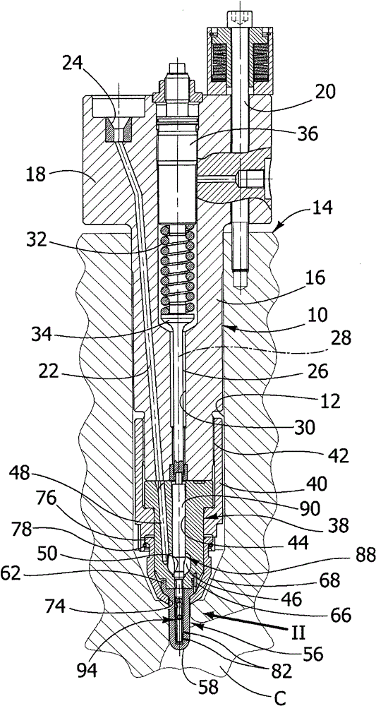
[0026] see figure 1 , Reference numeral 10 denotes a fuel injector for a diesel engine of the present invention. The injector 10 is intended to fit into an axially long cavity 12 formed in a head 14 of the engine. The injector 10 includes an elongated housing 16 having at its top an enlarged head 18 which protrudes outside the lumen 12 and is capped with a screw 20 ( figure 1 Only one of the screws is visible) to the engine head 14.

[0027] In the following description and claims, the terms "above", "below", "top", "bottom" and the like refer to the normal usage position of injector 10 . However, it is contemplated that injector 10 could be mounted in a more or less inclined position with respect to the vertical axis.

[0028] A fuel supply conduit 22 is formed in the housing 16 and is connected at its upper end to an opening 24 which is connected to a fuel supply line (not shown). The propulsion element 26 is axially movable along the longitudinal axis 28 inside a throug...


PUM


Abstract

A fuel injector for internal combustion engines, comprising: - a housing (16), - a valve guide (38) fixed at a lower end of said housing (16), the valve guide (38) having a longitudinal guide bore (44) and a chamber (46) provided with a valve seat (50), said chamber (46) being connected to a fuel supply duct (22,48); - an atomizer (56) fixed at a lower end of said valve guide (38), the atomizer (56) having a longitudinal bore (80) in flow connection with said chamber (46), the atomizer having a plurality of nozzle bores (82) having inlet openings (84) facing into said longitudinal bore (80); - a spindle (88) having a valve portion (92) cooperating with said valve seat (50), and a cut-off element (94) extending into said longitudinal bore (80) of the atomizer (56), wherein an upper cut-off section (102) and a lower cut-off section (106) axially spaced apart from each other are defined between the outer surface of the cut-off element (94) and the inner surface of the longitudinal bore (80), cut-off sections (102,106) being both closed in the closed position of the spindle (88), the cut-off element (94) having a central duct (112) in flow connection with the longitudinal bore (80) of the atomizer (56) both above the upper cut-off section (102) and below the lower cut-off section (106).

Description

technical field [0001] The present invention relates to fuel injectors for internal combustion engines. In particular the invention relates to fuel injectors for large two-stroke internal combustion engines, such as diesel engines for marine propulsion. [0002] More precisely, the invention relates to a fuel injector according to the preamble of claim 1, comprising a housing, a valve guide, an atomizer, a spindle, and a shut-off element, said valve guide being fixed at the lower end of the housing , the atomizer is fixed at the lower end of the valve guide and is provided with a plurality of nozzle holes, the mandrel has a valve portion that fits into the valve seat of the valve guide, and the shut-off element extends into the longitudinal hole of the atomizer so that The volume fluidly connected to the nozzle bore is reduced when the mandrel is in the closed position. Background technique [0003] EP-A-052937 discloses a fuel injector comprising an axially displaceable m...

Claims


Application Information

Patent Timeline
Patent Type & Authority Patents(China)
IPC IPC(8): F02M61/04F02M61/18F02M53/04
CPCF02M61/042F02M61/06F02M61/182F02M61/1893F02M61/10F02M61/1866
Inventor P·米奥蒂M·德斯特罗M·科波L·福米亚M·加拉谢M·洛姆巴多
Owner WAERTSILAE SWITZERLAND
Why Eureka
Try Eureka