
Method and device for detecting end surface of optical fiber connector

A fiber optic connector and detection method technology, applied in the direction of measuring devices, optical devices, optical instrument testing, etc., can solve the problems of surface damage and pollution of the tested part, difficulty in measuring the end face of the optical fiber, damage to structural components, etc., and achieve automation High, strong anti-interference ability and accuracy, easy to use effect

Inactive Publication Date: 2010-10-06
ZHEJIANG NORMAL UNIVERSITY
View PDF2 Cites 30 Cited by
  • Summary
  • Abstract
  • Description
  • Claims
  • Application Information

AI Technical Summary

Problems solved by technology

[0003] The traditional method of measuring the end face of the fiber optic connector is the microscopic imaging method, but the measurement accuracy of this method is not high
Interferometry measurement can improve the measurement accuracy compared with microscopic imaging method. Newton ring interferometry detection is the commonly used method. Damage, as well as damage and contamination of the surface of the tested part
Since the fiber end face of the finished fiber optic connector is packaged in FC / PC (or SC / PC, ST / PC), this also brings difficulties to the direct measurement of the fiber end face

Method used


Image

  • Method and device for detecting end surface of optical fiber connector
  • Method and device for detecting end surface of optical fiber connector
  • Method and device for detecting end surface of optical fiber connector

Examples


Embodiment Construction

[0017] The present invention will be further described below in conjunction with the accompanying drawings and embodiments.

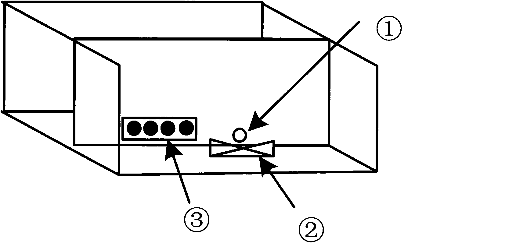
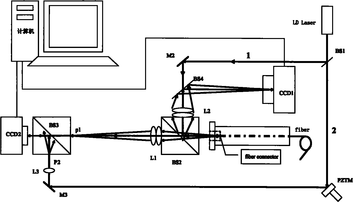
[0018] figure 1 It is a schematic diagram of the appearance of the present invention. The light entrance ① of the optical fiber connector is the optical interface between the end face of the optical fiber connector under test and the device of the present invention; the fixing frame ② of the optical fiber connector is used to fix the optical fiber connector under test; transfer interface. figure 2 The light signal of the middle laser light source LD is split, wherein the light path 1 is the reference light path, and the light path 2 is the object light path. The reference light enters the CCD1 after being focused and reflected, and then sent to the computer through the USB interface ③. The object light is reflected and focused, and enters the end face of the optical fiber connector under test of the optical fiber connector fixing frame ② through the...


PUM


Abstract

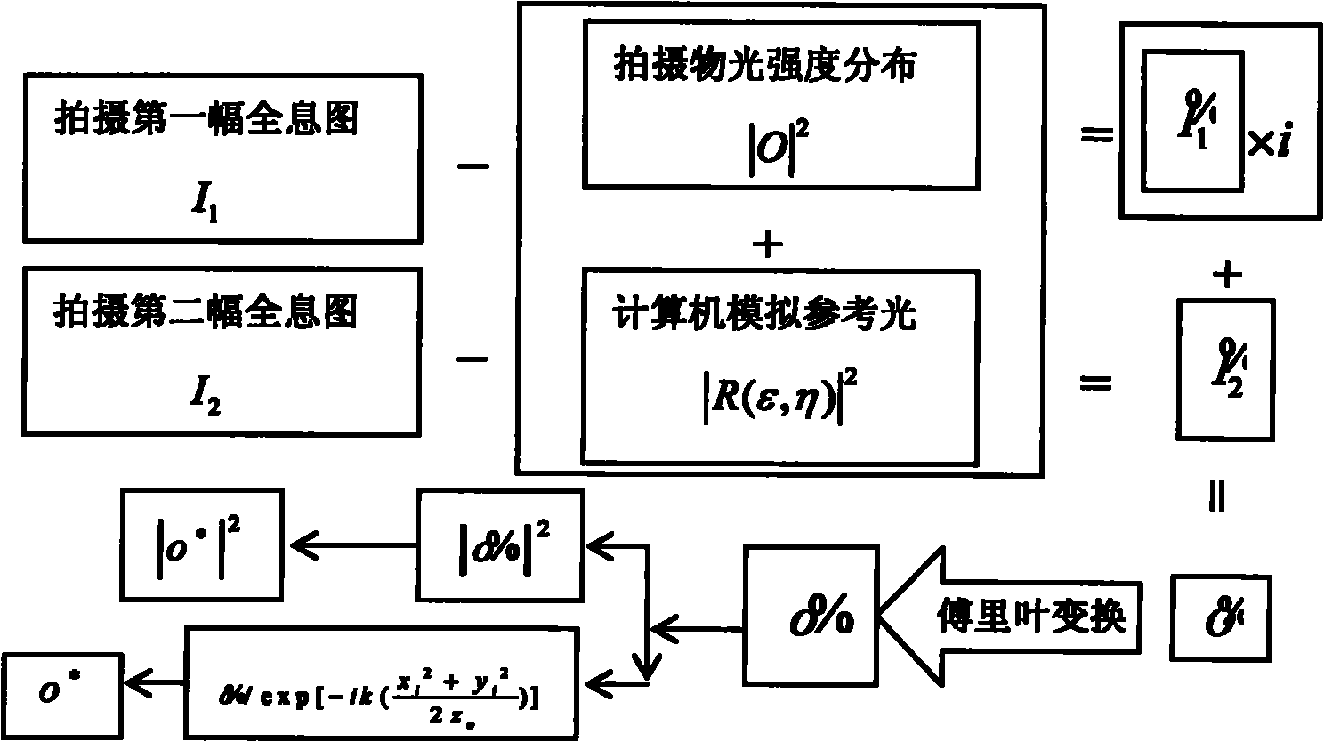
The invention relates to a detector for the end surface of an optical fiber connector. In the detector, an optical signal of a laser source is split into a reference light path and an object light path, wherein reference light is focused and reflected to enter into a photoelectric converter and then transmitted into a computer through a USB interface; object light is reflected and focused, and then enters to the end surface of a detected optical fiber connector on an optic fiber connector holder through a light incidence port of the optical fiber connector; the transmitted object light and the reflected reference light which are reflected and amplified by the optical signal interferes on the symmetrical surface of the incidence surface of a beam-splitting mirror on which the detected optical fiber is reflected, and then the transmitted object light and the reflected reference light are acquired by another photoelectric converter and transmitted into the computer through the USB interface; and after the optical signal is acquired, the computer carries out de-noising on a hologram by using software and reconstitutes a three-dimensional hologram according to a two-step phase shift method. The invention can not only detect parameters of ovality, concentricity, and the like of a connector fiber core and a connector cover, but also reconstitute the three-dimensional topography on the surface of the end surface fiber core area and monitor the surface appearance and the height of the fiber core; in addition, the invention has high detection accuracy, small system size and high automation degree and is friendly in a user interface and convenient to use.

Description

technical field [0001] The invention belongs to the technical field of digital holography for detecting the appearance of an optical fiber end face used in an optical fiber connector, in particular to a method and a device for detecting the end face of an optical fiber connector. technical background [0002] The geometric parameters of the end face of the fiber optic connector, such as the coordinates of the center of the fiber core, the offset of the vertex of the spherical surface, the unevenness of the surface, the height of the fiber core, the inclination angle of the end face, etc., are the main factors affecting the performance of the fiber optic connector. Therefore, in the actual production process of the connector, the accuracy of the end face of the optical fiber connector is very high, and it is necessary to detect the end face of the optical fiber connector in real time to ensure that various defect errors are within the allowable range. If there is a defect in ...

Claims


Application Information

Patent Timeline
IPC IPC(8): G01B11/00G01M11/00
Inventor 沈亚强王辉万旭彭保进金洪震马利红
Owner ZHEJIANG NORMAL UNIVERSITY
Learn More