Control system and method of liquid crystal display

A technology for liquid crystal displays and control systems, applied in static indicators, instruments, etc., can solve problems such as pixel charging errors, and achieve the effects of improving service life, avoiding charging errors, and solving clock signal delay problems.

Inactive Publication Date: 2010-10-06
AU OPTRONICS CORP
View PDF0 Cites 13 Cited by
  • Summary
  • Abstract
  • Description
  • Claims
  • Application Information

AI Technical Summary

Problems solved by technology

[0005] In view of this, it is necessary to provide a control method of a liquid crystal display, wh

Method used


Image

  • Control system and method of liquid crystal display
  • Control system and method of liquid crystal display
  • Control system and method of liquid crystal display

Examples


Embodiment Construction

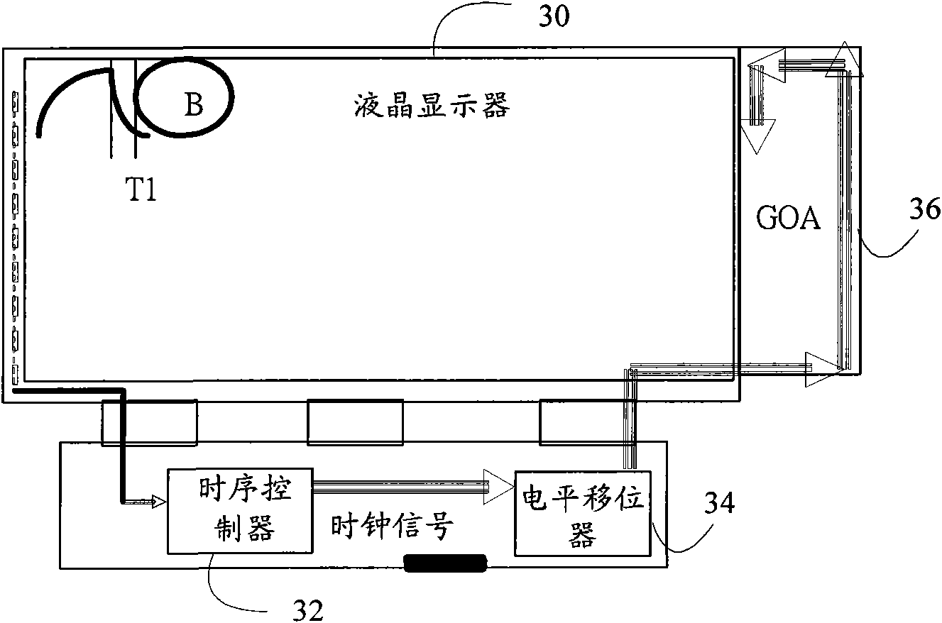
[0025] Figure 3a and 3b It is a schematic diagram of the application environment of the liquid crystal display control method according to an embodiment of the present invention. Wherein, the timing controller 32 is connected to the level shifter 34, the level shifter 34 is connected to an array substrate line driver (Gate Driver on Array; GOA) 36, the GOA 36 is connected to the liquid crystal display 30, and the liquid crystal display 30 is also connected to all The timing controller 32 is described.

[0026] In this embodiment, the timing controller 32 is used to output the first clock signal and a pulse signal, and receive a feedback signal of a pixel point B of the liquid crystal display, and judge whether to output the first clock signal according to the feedback signal. Two clock signals. In this embodiment, the timing controller 32 is used to generate and transmit the first clock signal and the pulse signal to the level shifter 34 . The level shifter 34 is connecte...


PUM


Abstract

The invention relates to a control system of a liquid crystal display, which is used in the liquid crystal display, and comprises a timing controller, a level shifter and an array substrate column driver, wherein the timing controller is connected with the liquid crystal display and is used for outputting first clock signals and pulse signals, receiving feedback signals of pixels, and judging whether second clock signals are output or not according to the feedback signals, and the level shifter is connected with the timing controller and providing the liquid crystal display with charging signals according to the first clock signals and the second clock signals respectively; and the array substrate column driver is connected with the liquid crystal display and the level shifter, and is used for transmitting driving signals according to the charging signals respectively to control the charging of the pixels of the liquid crystal display. The invention also provides a control method of the liquid crystal display, which can solve the problems of charging error of the pixels caused by signal transmission delay in the liquid crystal display.

Description

technical field [0001] The invention relates to a liquid crystal display, and in particular to a control system of the liquid crystal display. Background technique [0002] At present, in order to reduce the manufacturing cost of liquid crystal displays, liquid crystal display manufacturers have begun to develop the Gate Driver on Array (GOA) technology, that is, to directly fabricate the gate driver ICs on the array (Array) substrate to Instead of driver chips made of external silicon chips. The application of this technology can reduce the production process procedure, reduce the product process cost, and improve the integration degree of the liquid crystal display panel. [0003] However, in the GOA technology, the clock driving signal transmitted to the gate line of the liquid crystal display will be affected by parasitic capacitance when passing through each stage of shift register, which will cause the delay of the clock driving signal on the bus, and As a result, th...

Claims


Application Information

Patent Timeline
IPC IPC(8): G09G3/36
Inventor 郑晓锺萧开元
Owner AU OPTRONICS CORP
Why Eureka
Try Eureka