Magnetron for microwave oven

A technology for magnetrons and microwave ovens, applied in the field of magnetrons, can solve the problems of being unable to suppress and not considering the suppression of noise, and achieve the effect of suppressing noise

Active Publication Date: 2010-10-06
TOSHIBA HOKUTO ELECTRONICS CORP
View PDF6 Cites 6 Cited by
  • Summary
  • Abstract
  • Description
  • Claims
  • Application Information

AI Technical Summary

Problems solved by technology

However, the electromagnetic wave (unwanted noise) in the adjacent low frequency band outside the ISM frequency band (2400-2500MHz) that is prohibited from leaking from the microwave oven according to the Radio Wave Law cannot be suppressed by the choke
[0007] Here, in Patent Document 1, although the design values ​​of the inner diameter of the through hole of a pair of pole pieces and the outer diameter of the bottom are studied, the diameter of the output side is the same as the diameter of the input side, and the ISM is not considered. Suppression of unnecessary noise in the adjacent low frequency band (2300-2400MHz) out of the frequency band

Method used


Image

  • Magnetron for microwave oven
  • Magnetron for microwave oven
  • Magnetron for microwave oven

Examples


Embodiment Construction

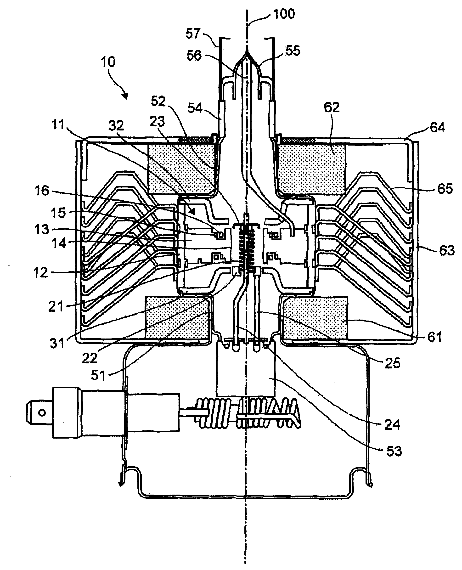
[0057] use Figure 1 to Figure 13 A magnetron according to an embodiment of the present invention will be described.

[0058] First, use figure 1 The schematic structure of the magnetron of this embodiment is demonstrated. figure 1 It is a schematic vertical cross-sectional view along the tube axis direction of the magnetron according to the embodiment of the present invention.

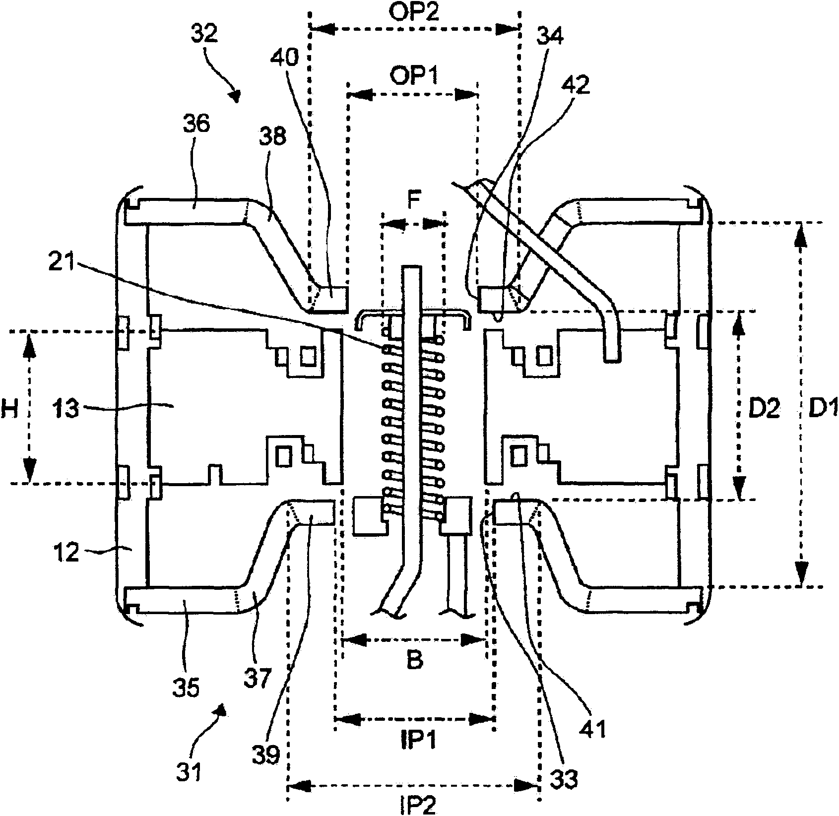
[0059] The anode part 11 has an anode cylinder 12 and ten fins 13 . The cylindrical anode cylinder 12 extends in the direction of the tube axis 100 which is the central axis of the magnetron 10 . One side of the ten plate-shaped fins 13 is joined to the inner wall of the anode cylinder 12 , and the other side is a free end. The free ends of the fins 13 are disposed on the same cylindrical surface extending along the tube axis 100, and this cylindrical surface is called the fin inscribed cylindrical surface 14. Ten fins 13 are inscribed on the cylindrical surface 14 from the fins. to the inner wal...


PUM


Abstract

Unnecessary noises generated from a magnetron for a microwave oven are suppressed. In a magnetron 10 for a microwave oven, the diameter IP1 of the through-hole 33 of the input side pole piece 31 is 8.6 to 9.1 mm and the outer diameter IP2 of the internal surface 41 of the input side pole piece 31 is 15 to 16 mm, while the diameter OP1 of the through-hole 34 of the output side pole piece 32 is 7.9 to 8.1 mm and the outer diameter OP2 of the internal surface 42 of the output side pole piece 32 is 11 to 13 mm. Additionally, the interval distance D1 between the outer annular portion 35 of the input side pole piece 31 and the outer annular portion 36 of the output side pole piece 32 is 11.5 to 13.5 mm and the interval distance D2 between the inner annular portion 39 of the input side pole piece 31 and the inner annular portion 40 of the output side pole piece 32 is 10.2 to 11.2 mm.

Description

technical field [0001] The invention relates to a magnetron used in a microwave oven. Background technique [0002] An oscillating unit of a magnetron for microwave ovens (hereinafter simply referred to as “magnetron”) has an anode unit composed of an anode cylinder and vanes (Japanese: bein) and a cathode unit composed of a spiral filament. The oscillator generates not only fundamental waves in the ISM band (2400 to 2500 MHz) but also electromagnetic waves in frequency bands other than the ISM band. [0003] A pair of funnel-shaped pole pieces are arranged facing each other, and are joined to the ends of the anode cylinder, respectively. Furthermore, the pair of metal sealing bodies are joined to the ends of the pair of pole pieces, respectively. An insulating cylinder is joined to the end of the metal sealing body on the output side, and an exhaust pipe is joined to the end of the insulating cylinder. An antenna emerges from one of the fins, the front end of which is cl...

Claims


Application Information

Patent Timeline
Patent Type & Authority Applications(China)
IPC IPC(8): H01J25/50H01J23/02H01J23/11
CPCH01J23/10H01J25/587
Inventor 加藤直也
Owner TOSHIBA HOKUTO ELECTRONICS CORP
Why Eureka
Try Eureka