Power-on circuit for washing machine and power-on method thereof

A washing machine and circuit technology, applied in the field of washing machines, can solve problems such as limitations, and achieve the effects of simple structure, convenient use, and avoiding damage to keys

Inactive Publication Date: 2010-10-13
WHIRLPOOL CHINA
View PDF0 Cites 15 Cited by
  • Summary
  • Abstract
  • Description
  • Claims
  • Application Information

AI Technical Summary

Problems solved by technology

[0007] From the above four methods, it can be found that no matter which method requires a mechanical operation process to achieve full-level power off, especially the first two methods must be mechanically operated again after the en

Method used


Image

  • Power-on circuit for washing machine and power-on method thereof
  • Power-on circuit for washing machine and power-on method thereof
  • Power-on circuit for washing machine and power-on method thereof

Examples


Example Embodiment

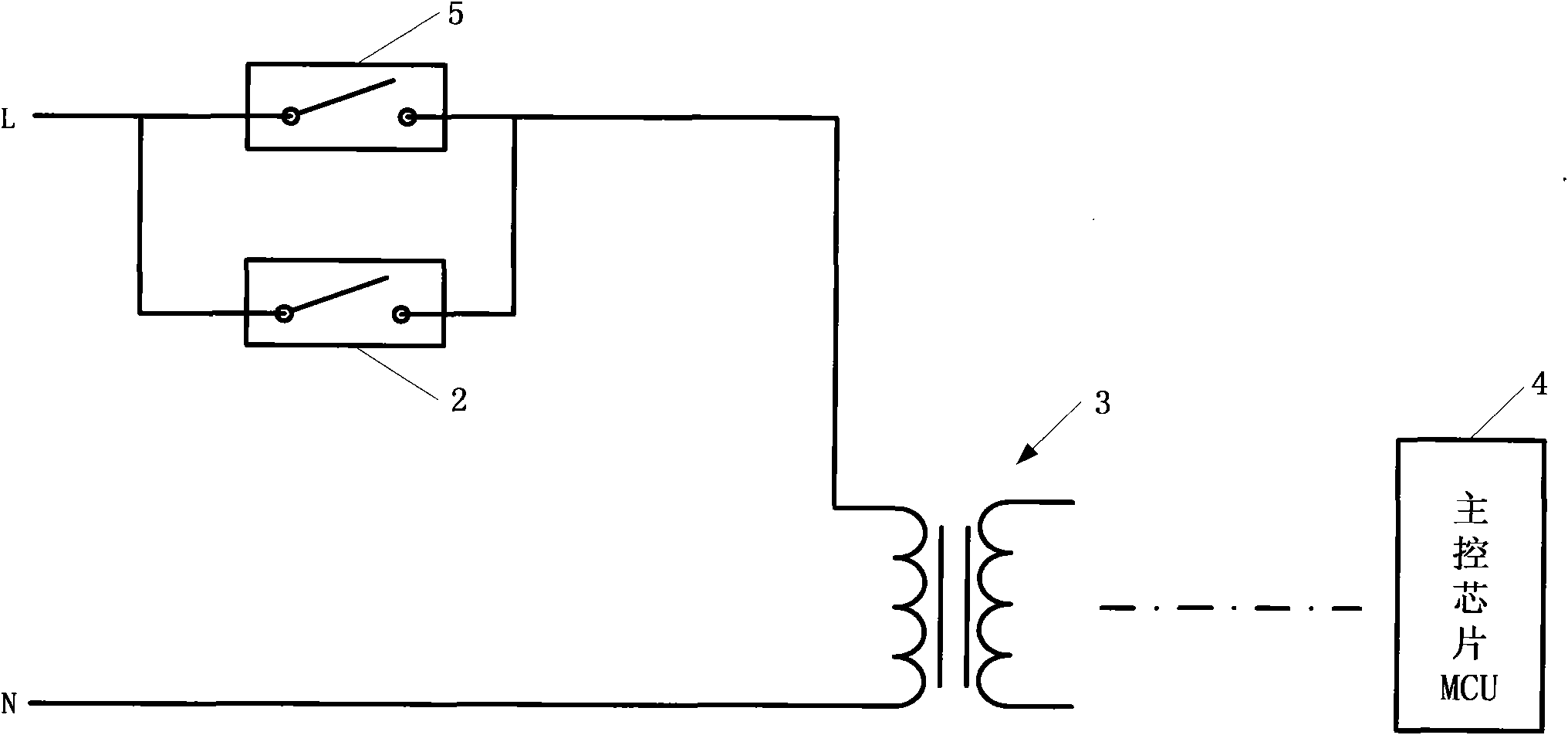
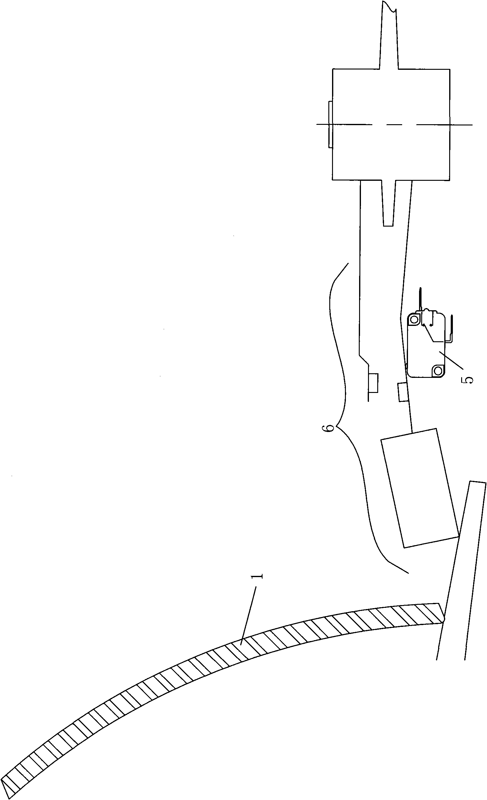
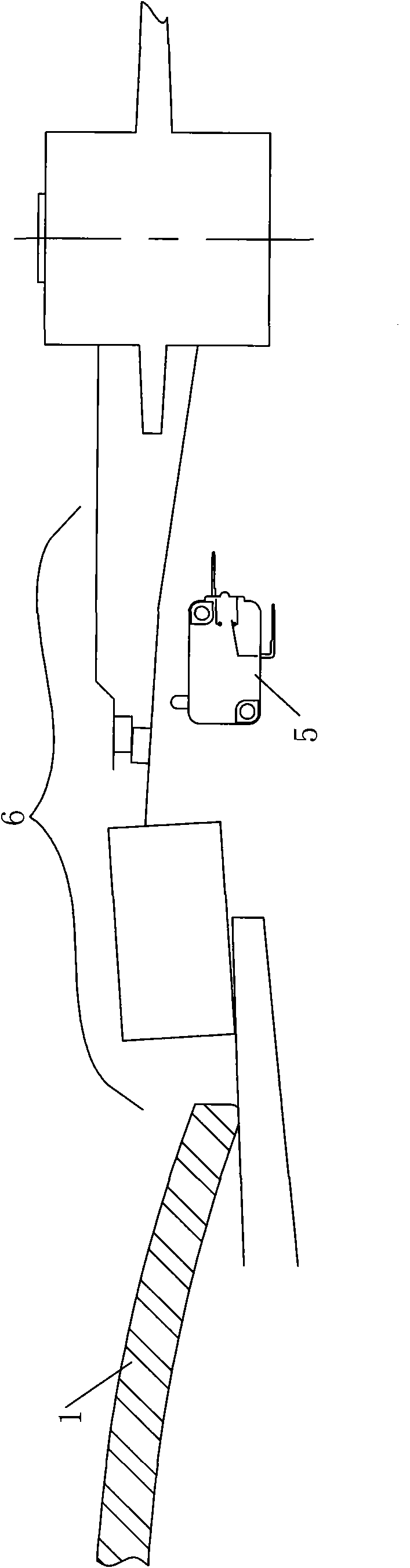
[0015] A power-on circuit for a washing machine includes a door cover 1 hinged to a washing machine body, and a control panel that can be operated by a user, the control panel is provided with touch buttons, and the washing machine body is in contact with the door cover 1 A linkage switch is arranged at the position of the door lock or in the keyhole of the door lock. The linkage switch is connected in parallel with the main control relay 2 and is connected with the main control chip MCU 4 through the transformer 3 . For the pulsator washing machine, the linkage switch includes a safety switch assembly 6 disposed below the door cover 1 and in contact with the lower end surface of the door cover 1, and a safety switch assembly 6 disposed below the safety switch assembly 6 and in the stroke of the safety switch assembly 6 The micro switch 5 inside, the safety switch assembly 6 is linked with the micro switch 5, the micro switch 5 is connected in parallel with the main control rel...


PUM


Abstract

The invention relates to a powder-on circuit for a washing machine. The circuit comprises a door cover plate and a control panel, wherein the door cover plate is hinged with a washing machine body; the control panel can be used for a user to operate; the control panel is provided with a touch key; a linked switch is arranged at the position where the washing machine body is contacted with the door cover plate or in a lock hole of a door lock; and the linked switch is connected with a master relay in parallel and is connected with a main control unit (MCU) through a transformer. The invention also discloses a power-on method for the power-on circuit of the washing machine. In the circuit and the method, the linked switch which can control the power on of the control panel is arranged on the washing machine body, and linkage is realized by the linked switch and an opening action of the door cover plate or the door lock; and when the door cover plate or the door lock is open, the MCU supplies power to the control panel so that the overall control panel becomes more coordinate and beautiful. The power-on circuit has the characteristics of high waterproofness, simple structure and convenient use, and can avoid a key damage phenomenon caused by long-term use.

Description

technical field [0001] The invention relates to the technical field of washing machines, in particular to a washing machine power-on circuit and a power-on method thereof. Background technique [0002] Due to the requirements of standby energy consumption and safe use, the washing machine industry gradually requires the product to have the function of all-pole power-off. In short, the live wire is in a power-off state when the power switch is not pressed, and is not connected until the power switch is turned on. into the circuit. Currently, there are several ways to achieve the above functions: [0003] First, a mechanical switch with a separate reciprocating mechanism is used: when power is required, press the mechanical switch to establish a power-on circuit, and execute power-on through the program; when power-off is required, press the mechanical switch again to return to the original position, and the power is cut off . [0004] Second, a rotary encoding switch integ...

Claims


Application Information

Patent Timeline
IPC IPC(8): D06F37/28D06F37/00D06F33/02H01H9/20
Inventor 金友华杨宇澄黄秋宏朱腾飞姚晓倩
Owner WHIRLPOOL CHINA
Why Eureka
Try Eureka