Unlock instant, AI-driven research and patent intelligence for your innovation.

End-pumped solid laser

A solid-state laser, end-pumped technology, applied in the field of lasers, can solve the problems of laser resonator misalignment, laser misalignment, no light, etc., to avoid thermal deformation, laser stabilization, and improve stability.

Active Publication Date: 2012-10-17
ZHEJIANG JIATAI LASER SCI & TECH CO LTD
View PDF0 Cites 0 Cited by
  • Summary
  • Abstract
  • Description
  • Claims
  • Application Information

AI Technical Summary

Problems solved by technology

The mirror frame of this structure is small in size and easy to adjust. However, in industrial products, due to the relatively poor environment and large temperature difference, the mirror frame cannot be directly fixed in the optical path, but needs to be fixed on the connecting plate first, and then can be used. It is fixed on the base of the optical path, so it is more obviously affected by thermal expansion and contraction, which can change the deformation of the tension spring and make the laser resonator out of adjustment
[0003] In the end-pumped solid-state laser with folded structure, its overall structure is relatively compact, but its optical parts are relatively complicated, and its misalignment stability is poor. , will make the laser more unstable, affect the stability of the laser output power, and even not emit light in severe cases
[0004] The end-pumped solid-state laser with ordinary linear flat cavity structure has a simple and practical structure and good beam quality. However, since the pump light cannot be completely absorbed by the laser working material, the unabsorbed pump light will be directed to the output coupling The output coupling mirror is thermally deformed due to the irradiation of unabsorbed pump light, which makes the laser out of tune and affects the stability of the laser
At the same time, the output mirror frame is also heated and deformed, which makes the laser resonator out of adjustment

Method used


Image

  • End-pumped solid laser
  • End-pumped solid laser
  • End-pumped solid laser

Examples


Embodiment Construction

[0018] The present invention will be further described below in conjunction with the accompanying drawings and specific embodiments.

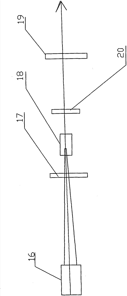
[0019] Such as figure 1 As shown, the present embodiment includes a pumping source 16, a gain medium 18, a resonant cavity, and an aperture 20. The resonant cavity is mainly composed of a total reflection mirror 17, a planar output coupling mirror 19 and its fine-tuning mirror holder. The gain medium 18 is arranged on the optical path between the planar output coupling mirror 19 and the total reflection mirror 17, and the described aperture 20 is arranged on the optical path between the described gain medium 18 and the planar output coupling mirror 19, and the optical The aperture of the aperture 21 in the diaphragm 20 is 1.5mm (as Figure 5 shown).

[0020] Although the light-to-light conversion efficiency is high in the end-pumped laser, there will always be part of the unabsorbed pump light passing through the gain medium 18. In the laser ...


PUM


Abstract

The invention relates to a laser, in particular to an end-pumped solid laser with high stability. A resonant cavity of the end-pumped solid laser mainly comprises a totally reflecting mirror, a plane output coupling mirror and a micro-adjustment mirror bracket thereof. The end-pumped solid laser is characterized in that the micro-adjustment mirror bracket comprises a mirror frame, a mirror holderand an adjusting screw, wherein the mirror frame comprises a flange and a lens mounting seat with spherical appearance, and a mirror frame mounting hole which is matched with the mirror frame is arranged on the mirror holder; the mirror frame mounting hole comprises a first mounting hole matched with the flange and a second mounting hole matched with a lens mounting seat, wherein the first mounting hole is in clearance fit with the flange, the second mounting hole is a conical hole, and the second mounting hole and the appearance sphere of the lens mounting seat form linear-planar fit connection; and the adjusting screw passes through a through hole in the mirror holder, is in threaded connection with the flange and articulated with the front end of the through hole in the mirror seat. The invention aims at designing the end-pumped solid laser with high power stability. Compared with the prior art, the invention has the advantages of large lens adjustment angle, convenient adjustment,good heat dissipation effect of the mirror bracket, stable power, and the like.

Description

technical field [0001] The invention relates to a laser, in particular to a highly stable end-pumped solid-state laser. Background technique [0002] At present, an end-pumped solid-state laser includes a pump source, a resonant cavity, and a gain medium. The resonant cavity is mainly composed of a planar total reflection mirror, a planar output coupling mirror and its fine-tuning mirror frame. The structure is compact, so most of the end-pumped solid-state lasers generally use a spring and screw structure on the frame to fine-tune the adjustment of each lens in the laser. The adjustment frame includes an "L"-shaped fine-tuning frame, a frame, left and right adjustment screws, Pitch adjustment screws and several tension springs, the corners of the "L" type micro-adjustment frame are hinged with the frame, the left and right adjustment screws are threaded with the horizontal adjustment bracket in the "L" type micro-adjustment frame, and the tail ends of the left and right adj...

Claims


Application Information

Patent Timeline
Patent Type & Authority Patents(China)
IPC IPC(8): H01S3/16H01S3/091H01S3/086H01S3/139
Inventor 郑宣成钟正根
Owner ZHEJIANG JIATAI LASER SCI & TECH CO LTD