Minitype electromagnetic broadband vibration energy collector

A vibration energy collection, electromagnetic technology, applied in the direction of electrical components, electromechanical devices, etc., can solve the problem of large device size, achieve the effect of large induced electromotive force and low process requirements

Inactive Publication Date: 2012-11-21
SHANGHAI JIAOTONG UNIV
View PDF0 Cites 2 Cited by
  • Summary
  • Abstract
  • Description
  • Claims
  • Application Information

AI Technical Summary

Problems solved by technology

The permanent magnets, cantilever beams, and brackets of the energy harvester are all assembled, and the device is bulky and cannot be integrated with micro wireless products and micro-electromechanical system devices.

Method used


Image

  • Minitype electromagnetic broadband vibration energy collector
  • Minitype electromagnetic broadband vibration energy collector
  • Minitype electromagnetic broadband vibration energy collector

Examples


Embodiment 1

[0032] A miniature electromagnetic broadband vibration energy harvester with three permanent magnets to form a vibration pickup structure

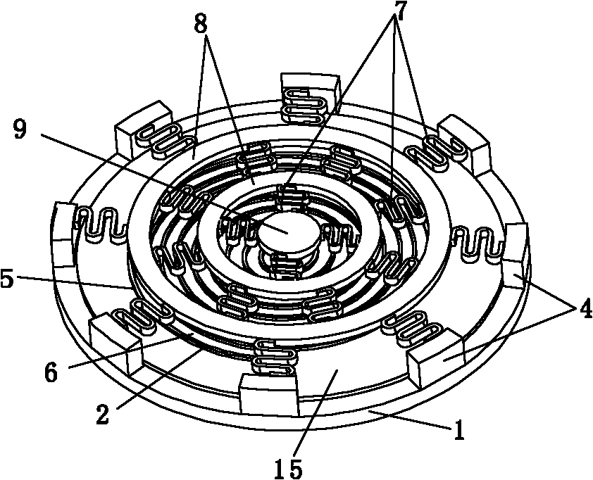
[0033] Such as figure 1 As shown, this embodiment includes: an insulating substrate 1, a planar spiral induction coil 2, a vibration pickup structure 3 and 8 supporting structures 4, wherein: the insulating substrate 1, the planar spiral induction coil 2 and the vibration pickup structure 3 are sequentially lower right On the other hand, the support structure 4 is located outside the planar spiral induction coil 2 and the vibration pickup structure 3 and is fixedly connected to the insulating substrate 1 .

[0034] The insulating substrate 1 is made of quartz or glass.

[0035] The planar spiral induction coil 2 is an induction coil winding structure, specifically a square or circular multi-layer multi-turn spiral metal copper coil 5 combined in a spiral involute mode, wherein the height, width and turns of the metal copper coil 5 The di...

Embodiment 2

[0047] A miniature electromagnetic broadband vibration energy harvester with four permanent magnets forming a vibration pickup structure

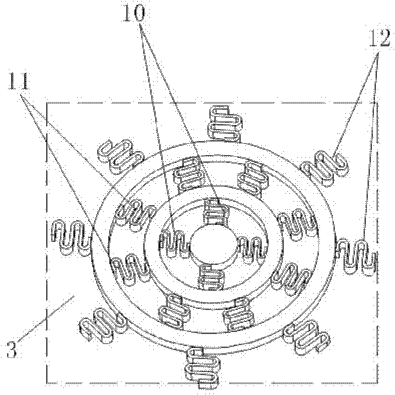
[0048] Such as image 3 As shown, four permanent magnets form a miniature electromagnetic broadband vibration energy harvester with a vibration pickup structure, its structure and principle are basically the same as in Embodiment 1, and the vibration pickup structure 3 includes: 28 serpentine springs 7 , 3 ring-shaped permanent magnets 8 and a center permanent magnet 9, wherein: the center permanent magnet 9 is located at the center of the vibration pickup structure 3, and the 3 ring-shaped permanent magnets 8 are connected to the outside of the center permanent magnet 9 from inside to outside in turn, and 28 snakes The shape spring 7 is radially arranged in the gap between the support structure 4, the annular permanent magnet 8 and the central permanent magnet 9 in turn, so that four vibration peaks can be displayed on the vibration spectr...

Embodiment 3

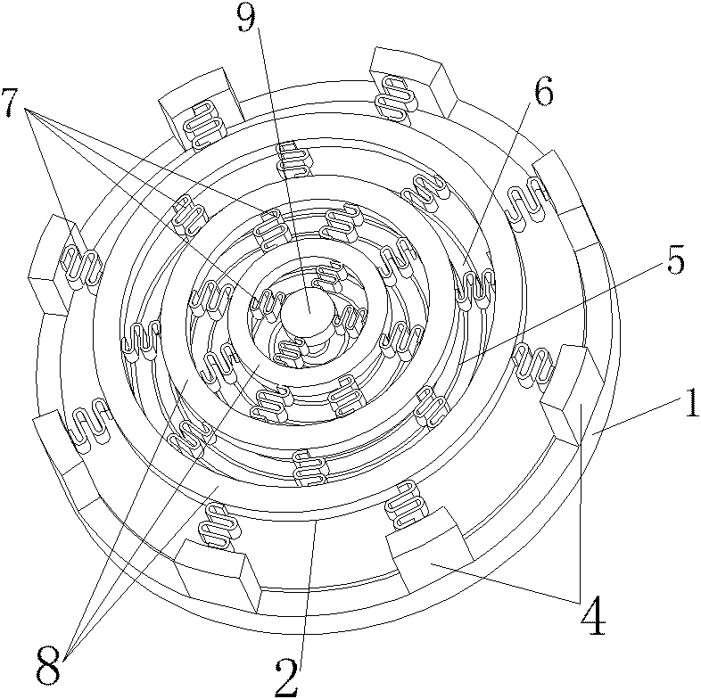
[0050] Such as Figure 4 As shown, this embodiment includes: an insulating substrate 1, a planar spiral induction coil 2, a vibration pickup structure 3, and a support structure 4, wherein: the insulating substrate 1, the planar spiral induction coil 2, and the vibration pickup structure 3 are sequentially lower right to upper Fixedly arranged, the support structure 4 is located outside the planar spiral induction coil 2 and the vibration pickup structure 3 and is fixedly connected with the insulating substrate 1 to form an I-shaped integrated structure.

[0051] The height of the I-shaped integrated structure is 1500 microns, and the amplitude of its fixed frequency is close to that of the planar spiral induction coil 2 .


PUM


Abstract

The invention relates to a minitype electromagnetic broadband vibration energy collector, which belongs to the technical field of micro electromechanical systems. The minitype electromagnetic broadband vibration energy collector comprises an insulating substrate, a planar spiral induction coil, a vibration pick-up structure and a support structure, wherein the insulating substrate, the planar spiral induction coil and the vibration pick-up structure are orderly arranged from the right lower part to the upper part; and the support structure is positioned on the outer side of the planar spiral induction coil and the vibration pick-up structure and fixedly connected with the insulating substrate. The invention collects broadband energy by superposing vibration modes of a plurality of circular permanent magnets connected by springs, and realizes integrated manufacturing of permanent magnets by a microstructure graphical method. Since the graphical permanent magnet can have a thick microstructure, the graphical permanent magnet has higher energy collection and conversion efficiency compared with the electroplated permanent magnet. The invention is compatible with IC technique, and is easy to realize mass production.

Description

technical field [0001] The invention relates to a device in the field of micro-electromechanical systems, in particular to a miniature electromagnetic broadband vibration energy collector. Background technique [0002] As the wireless sensor network system gradually enters people's field of vision, it has broad application prospects in the fields of biomedicine, industry, construction, consumer electronics and national defense. However, as the size of wireless sensing products and MEMS devices continues to decrease, the power supply problem has become a major obstacle to their development and application. At present, people mainly rely on disposable batteries with high energy density. Although the energy storage density and service life of batteries are continuously improved, their defects are self-evident: large volume, high quality, limited life, and need to be replaced constantly. The service life of wireless sensor networks is often long, the nodes are widely distribute...

Claims


Application Information

Patent Timeline
Patent Type & Authority Patents(China)
IPC IPC(8): H02K33/18
Inventor 杨卓青陶凯丁桂甫王艳
Owner SHANGHAI JIAOTONG UNIV
Why Eureka
Try Eureka