

Magnetic integration transfer circuit system
A conversion circuit and magnetic integration technology, which is applied in the field of magnetic integration conversion circuit system, can solve the problems of space occupation and large auxiliary circuit of power supply, etc., and achieve the effect of simplification and reduction of space volume
- Summary
- Abstract
- Description
- Claims
- Application Information
AI Technical Summary
Problems solved by technology
Method used
Image

Examples
Embodiment 1
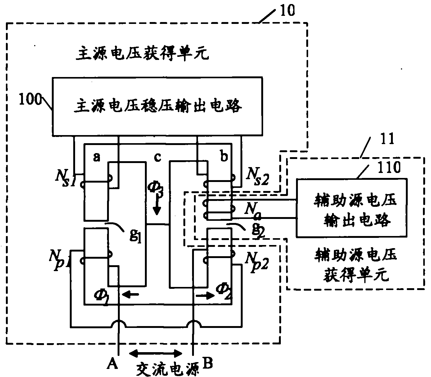
[0030] A magnetic integrated conversion circuit system, the structure diagram is as follows figure 2 As shown, it includes: a main source voltage obtaining unit 10 and at least one (one is taken as an example in this embodiment) auxiliary source voltage obtaining unit 11, wherein:
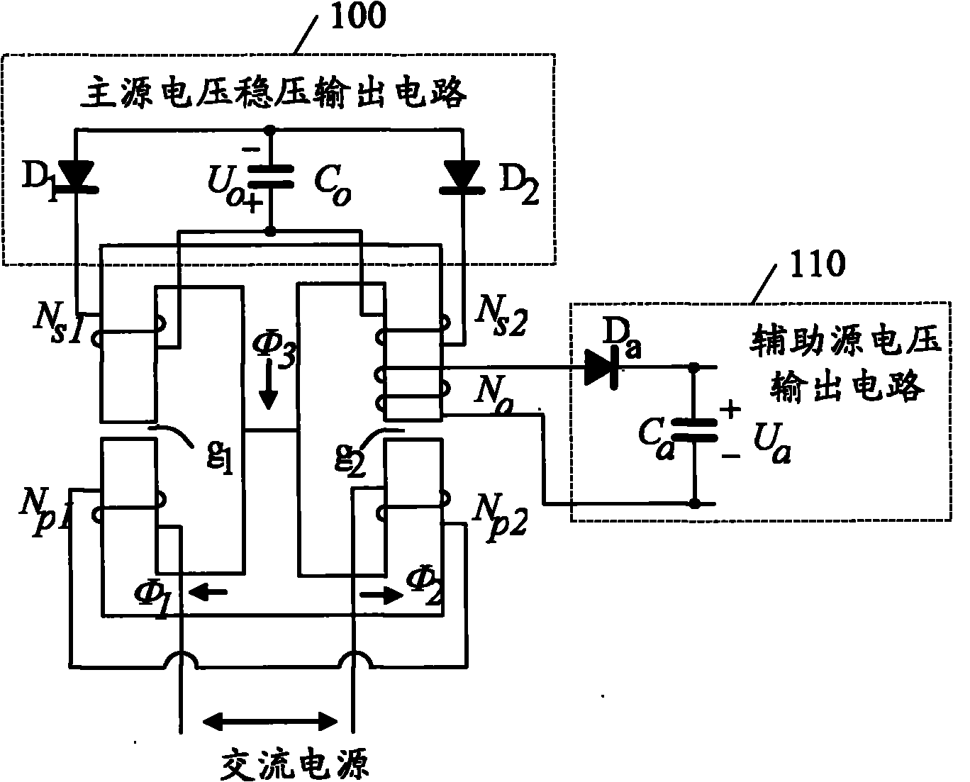
[0031] The main source voltage obtaining unit 10 includes an integrated magnetic component with at least three magnetic columns (the embodiment of the present invention takes three magnetic columns a, b and c as an example), a primary winding N p (including N in the figure p1 , N p2 ), at least two (the embodiment of the present invention takes two as an example) primary and secondary windings N s1 and N s2 And the main source voltage regulator output circuit 100;
[0032] The auxiliary source voltage obtaining unit 11 includes a secondary winding N a and auxiliary source voltage output circuit 110;
[0033] Primary winding N p The two ends A and B are connected to the input power supply, s...
Embodiment 2
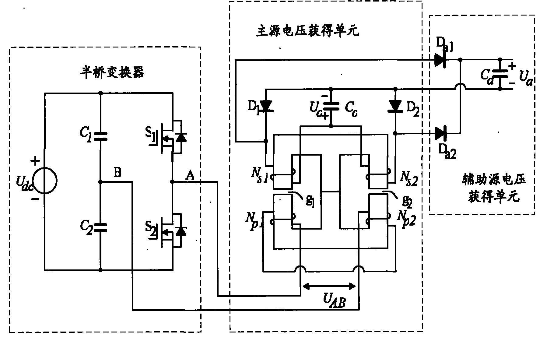
[0047] A magnetic integrated conversion circuit system. In this embodiment, the circuit system includes two auxiliary source voltage acquisition units. The schematic diagram of the structure is as follows: Figure 4 As shown, it includes: the main source voltage obtaining unit and two auxiliary source voltage obtaining units, where:
[0048] The main source voltage obtaining unit includes integrated magnetic parts with three magnetic columns, two primary sub-windings N p1 and N p2 The connected primary winding N p , two primary and secondary windings N s1 and N s2 And the main source voltage regulated output circuit; wherein the main source voltage regulated output circuit is realized by the following structure:
[0049] The first rectifier diode D 1 and primary and secondary windings N s1 Circuit 1 is formed in series, and the second rectifier diode D 2 and primary and secondary windings N s2 Circuit 2 is formed in series, and circuit 1 and circuit 2 are connected in ...
Embodiment 3
[0057] A magnetic integrated conversion circuit system, the structure diagram is as follows Figure 5 As shown, it includes: a main source voltage obtaining unit 20 and at least one (one is taken as an example in this embodiment) auxiliary source voltage obtaining unit 21, wherein:
[0058] The main source voltage obtaining unit 20 includes an integrated magnetic part having at least three (in this embodiment, three magnetic columns A, B and C are taken as an example) magnetic columns, a primary winding N p (including N p1 and N p2 ), more than two (in this embodiment, take two as an example) primary and secondary windings N s1 and N s2 And the main source voltage stabilized output circuit 200; the auxiliary source voltage obtaining unit 21 includes a secondary winding N a and auxiliary source voltage output circuit 210;
[0059] Primary winding N p (including N p1 , N p2 ) both ends E and F are connected to the input power supply, at least two primary and secondary wi...
PUM
 Abstract
Description
Claims
Application Information