
Lamp driving module assembling structure and lamp comprising same

A technology for driving modules and assembling structures, which is applied to the components of lighting devices, lampshades, lighting devices, etc., which can solve the problems of increasing the internal space of the lamp housing, affecting maintenance efficiency, increasing production and maintenance costs, and reducing the internal space. , Good electrical safety, and the effect of improving maintenance efficiency

Inactive Publication Date: 2010-10-13
OCEANS KING LIGHTING SCI&TECH CO LTD +1
View PDF4 Cites 5 Cited by
  • Summary
  • Abstract
  • Description
  • Claims
  • Application Information

AI Technical Summary

Problems solved by technology

[0003] (1) Since each component is dispersedly installed in the inner cavity of the lamp housing, it needs to be installed separately during production, and the process is numerous, and during maintenance, each dispersed component needs to be inspected separately, which affects maintenance efficiency;
[0004] (2) According to the installation structure characteristics of each component, installation positions of different structures need to be set inside the lamp housing, which is not convenient for unifying the manufacturing mold of the lamp housing, resulting in high mold manufacturing costs for the lamp housing;
[0005] (3) Due to the need to increase multiple installation positions, the internal space of the lamp housing of the lamp is increased in disguise, and the internal space of the lamp housing increases, and the manufacturing mold of the lamp housing also increases correspondingly, which also leads to high mold manufacturing costs of the lamp housing;
[0006] (4) Since each component is scattered in the inner cavity of the lamp housing, it is necessary to install heat dissipation elements for each component separately, which is inconvenient for centralized management of heat dissipation, resulting in increased production and maintenance costs

Method used


Image

  • Lamp driving module assembling structure and lamp comprising same
  • Lamp driving module assembling structure and lamp comprising same
  • Lamp driving module assembling structure and lamp comprising same

Examples


Embodiment Construction

[0023] In order to make the object, technical solution and advantages of the present invention clearer, the present invention will be further described in detail below in conjunction with the accompanying drawings and embodiments. It should be understood that the specific embodiments described here are only used to explain the present invention, not to limit the present invention.

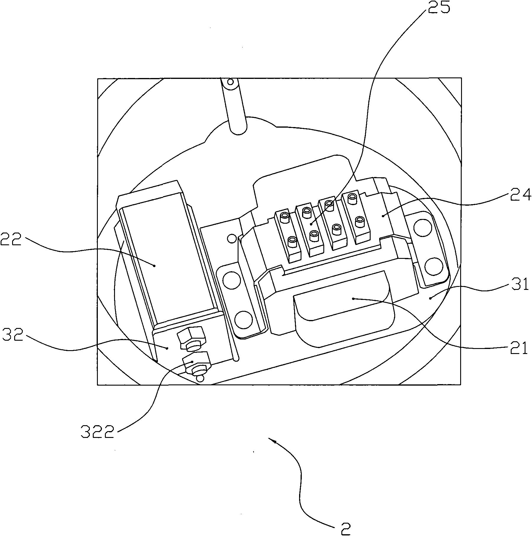
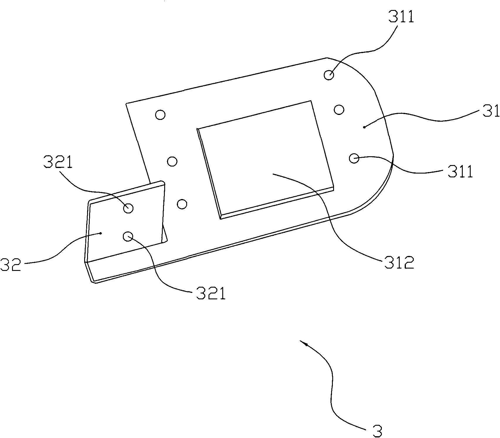
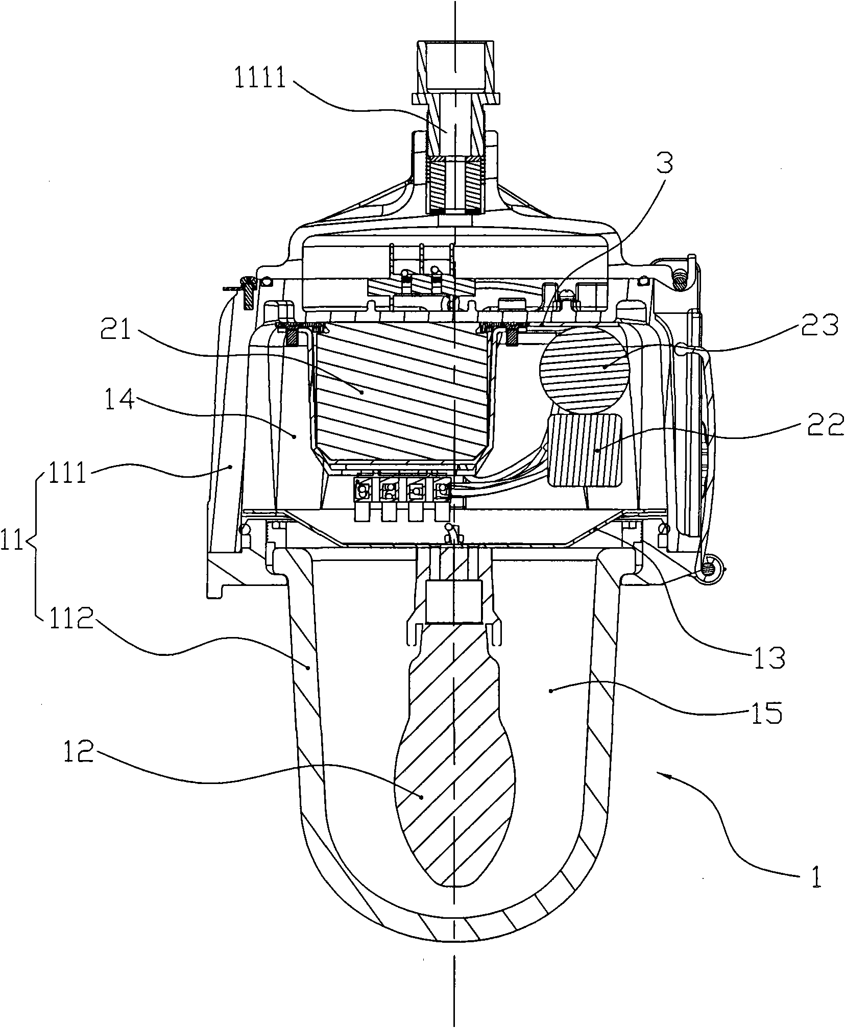
[0024] Such as Figure 1 ~ Figure 3 As shown, in the lamp driving module assembly structure provided by the embodiment of the present invention, the driving module 2 includes a ballast 21, a trigger 22 and a capacitor 23, and each component of the driving module 2 is collectively installed on a mounting bracket 3, and the mounting bracket 3 is installed in the lamp housing 11 of the lamp 1.

[0025] Different from the dispersed installation of the components of the drive module 2 in the prior art, the present invention firstly installs the components of the drive module 2 on the mounting bracket 3...


PUM


Abstract

The invention is applicable for the field of illuminating lamps, and provides a lamp driving module assembling structure. A driving module comprises a ballast, a trigger and a capacitor, wherein all the assemblies of the driving module are installed on an installing bracket in a centralized mode, and the installing bracket is installed in the lamp shell of the lamp. Through the centralized installation mode of the invention, the installed position inside the lamp shell is improved, the internal space of the lamp shell is reduced, and the size of the lamp is reduced on the basis of ensuring the unchanged illuminating brightness of the lamp; when in production, the driving module can be installed on the installing bracket in the centralized mode in advance, then the driving module and the installing bracket are installed in the lamp, thereby reducing the production working procedure of the lamp, and improving the production efficiency of the lamp; moreover, when a fault of the lamp occurs, the installing bracket and the driving module with the fault are directly taken out of the lamp, the new driving module and the new installing bracket are used instead of the installing bracket and the driving module with the fault, and then the driving module with the fault is maintained, thereby markedly improving the maintenance efficiency of the lamp.

Description

technical field [0001] The invention belongs to the field of lighting lamps, and in particular relates to an assembly structure of a lamp driving module and a lamp including the assembly structure. Background technique [0002] In the prior art, the lamp driving module mainly includes components such as ballasts, triggers, and capacitors. Usually, these components are scattered and installed in the inner cavity of the lamp housing. Although this installation method is relatively common, there are the following: question: [0003] (1) Since each component is dispersedly installed in the inner cavity of the lamp housing, it needs to be installed separately during production, and the process is numerous, and during maintenance, each dispersed component needs to be inspected separately, which affects maintenance efficiency; [0004] (2) According to the installation structure characteristics of each component, installation positions of different structures need to be set inside...

Claims


Application Information

Patent Timeline
Patent Type & Authority Applications(China)
IPC IPC(8): H05B41/14F21V23/00F21V3/02
Inventor 周明杰张建锋
Owner OCEANS KING LIGHTING SCI&TECH CO LTD
Learn More