
Eureka
For R&D, Eureka makes reading and utilizing patents & technical documents easy.
Eureka AIR
Designed for self-driven R&D workflows. Generate viable solutions, solve complex R&D challenges, empower your innovation with AI.

Eureka Materials
Designed for material experts only. Revolutionize your material R&D, from search, analyze, to developing new materials.

TechResearch
Generate reliable direction feasibility study reports for your R&D in just a few steps.

TechSeek
Discover and master advanced knowledge NOW. Basics, ideas, possibilities, all at once.

TechMind
As an expert in R&D Theories, TechMind can generates customized viable solutions instantly.

TechRisk
Analyze your overall solution with one click, know your potential R&D risks in advance.

TechMonitor
Get weekly tech updates, stay abreast of the latest tech innovations and key insights.
Electric blower and electric dust collector including the same
An electric blower and guide technology, applied in the direction of vacuum cleaners, machines/engines, liquid fuel engines, etc., can solve problems such as the difficulty of the impeller 132
- Summary
- Abstract
- Description
- Claims
- Application Information
AI Technical Summary
Problems solved by technology
Method used
Image

Examples
Embodiment approach 1
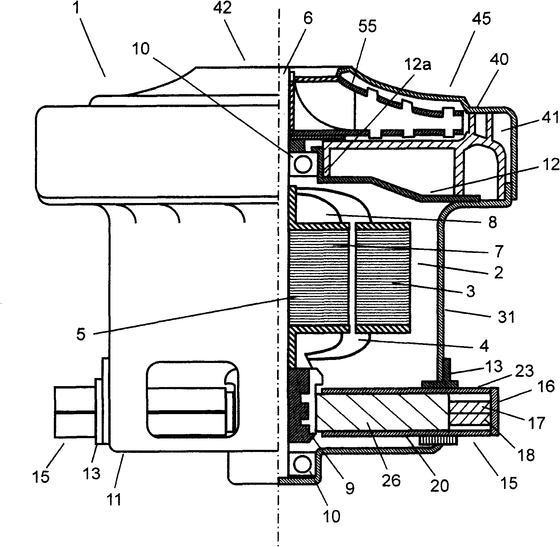
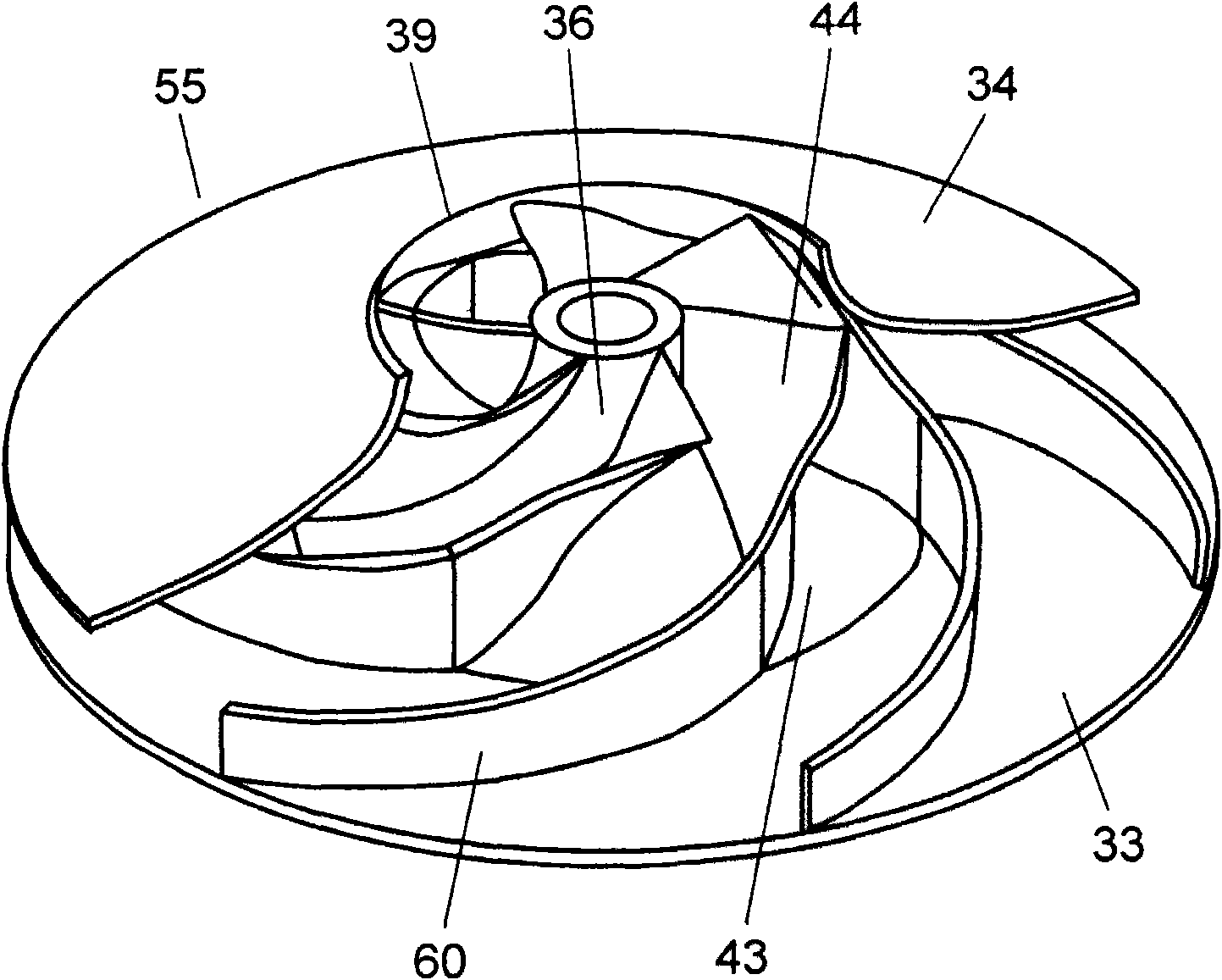
[0042] figure 1 It is a partial cross-sectional view of the electric blower according to Embodiment 1 of the present invention. figure 2 It is a perspective view with a part of the impeller of the electric blower cut away. Such as figure 1 As shown, the electric blower 1 has: the cover body 11 and the bracket 12 constituting the motor 31 ; and the housing 40 constituting the fan unit 45 . The housing 40 is attached to the bracket 12 in an airtight manner.
[0043] The motor 31 has a stator 2 and a rotor 5 . The stator 2 is configured by winding a field winding 4 around a magnetic core 3 . The stator 2 is attached to the inner surface of the casing 11 . The rotor 5 is configured by winding an armature winding 8 around an armature core 7 provided on a shaft 6 . The rotor 5 is rotatably attached to a cover 11 and a bracket 12 via bearings 10 provided at both ends of the shaft 6 . In addition, a commutator 9 is provided coaxially with the shaft 6 on the cover 11 side of ...
Embodiment approach 2
[0058] Image 6 It is a perspective view of the blade body of the impeller according to Embodiment 2 of the present invention. Figure 7 It is a perspective view of the blade of the impeller of this embodiment. In addition, the same code|symbol is attached|subjected to the same component as Embodiment 1, and detailed description is abbreviate|omitted.
[0059] Such as Image 6 with Figure 7 As shown, the blade 60 of this embodiment has a blade body 65 made of a metal plate, and a resin body 62 integrally formed on the outside of the blade body 65 . The blade body 65 has a plurality of openings 66 penetrating in the thickness direction. When the resin body 62 is integrally molded to the blade body 65 , the opening 66 is filled with the resin body 62 .
[0060] Thereby, the adhesion strength of the resin body 62 to the blade body 65 increases. That is, the resin body 62 is hard to peel off from the blade body 65 . Furthermore, the blade body 65 can be reduced in weight b...
Embodiment approach 3
[0062] Figure 8 It is a perspective view of the blade of the impeller in Embodiment 3 of this invention. In addition, the same reference numerals are assigned to the same components as those in Embodiment 1, and detailed description thereof will be omitted.
[0063] Such as Figure 8 As shown, the blade 70 of this embodiment has a blade body 61 and a resin body 72 integrally formed on the outside of the blade body 61 . In addition, as indicated by R in the figure, the cross section of the end portion of the resin body 72 has an arc shape. Figure 9A is a cross-sectional view of the riveted part of the impeller 55 . Figure 9B It is a sectional view other than the caulking part of the impeller 55 . The arc-shaped ends of the resin body 72 are in contact with the front guard 34 and the rear guard 33 . The arc shape of the resin body 72 is in smooth contact with the inner surfaces of the front shield 34 and the rear shield 33 .
[0064] When the electric blower 1 is energi...
PUM
 Abstract
Description
Claims
Application Information
 - R&D Engineer
- R&D Manager
- IP Professional
- Industry Leading Data Capabilities
- Powerful AI technology
- Patent DNA Extraction
Browse by: Latest US Patents, China's latest patents, Technical Efficacy Thesaurus, Application Domain, Technology Topic, Popular Technical Reports.
© 2024 PatSnap. All rights reserved.Legal|Privacy policy|Modern Slavery Act Transparency Statement|Sitemap|About US| Contact US: help@patsnap.com