Eureka AIR delivers breakthrough ideas for toughest innovation challenges, trusted by R&D personnel around the world.

Stepless mechanical lifting gear

A lifting device and mechanical technology, applied in the direction of lifting device, lifting frame, etc., can solve the problems of easy damage to the motor starting circuit, slow lifting speed, high cost, and achieve the effects of fast and comfortable use, improved work efficiency, and long service life.

Active Publication Date: 2010-10-20
SHANGHAI MEDIWORKS PRECISION INSTR CO LTD
View PDF0 Cites 6 Cited by
  • Summary
  • Abstract
  • Description
  • Claims
  • Application Information

AI Technical Summary

Problems solved by technology

Pneumatic or hydraulic lifting devices have high working stability, but the cost is also high, and they must be driven by active sources, which are noisy and difficult to maintain. Especially hydraulic lifting devices are prone to oil leakage and pollute the environment.
[0004] Although the structure of the electric lifting device is relatively simple, it needs to be used when there is a power supply. At the same time, when the motor is started, it will cause electromagnetic interference to the power grid and the surrounding environment, and there is a lot of noise, and the motor and its starting circuit are easily damaged (especially When the load is heavy), the scope of use is limited
[0005] Therefore, the mechanical lifting device has gradually become the mainstream trend of the industry, but most of the ordinary mechanical lifting devices use inclined plane mechanism, cam mechanism or screw mechanism, which makes the transmission efficiency of the lifting device low, the lifting speed is slow, and the lifting stroke is also limited.

Method used


Image

  • Stepless mechanical lifting gear
  • Stepless mechanical lifting gear
  • Stepless mechanical lifting gear

Examples


Embodiment Construction

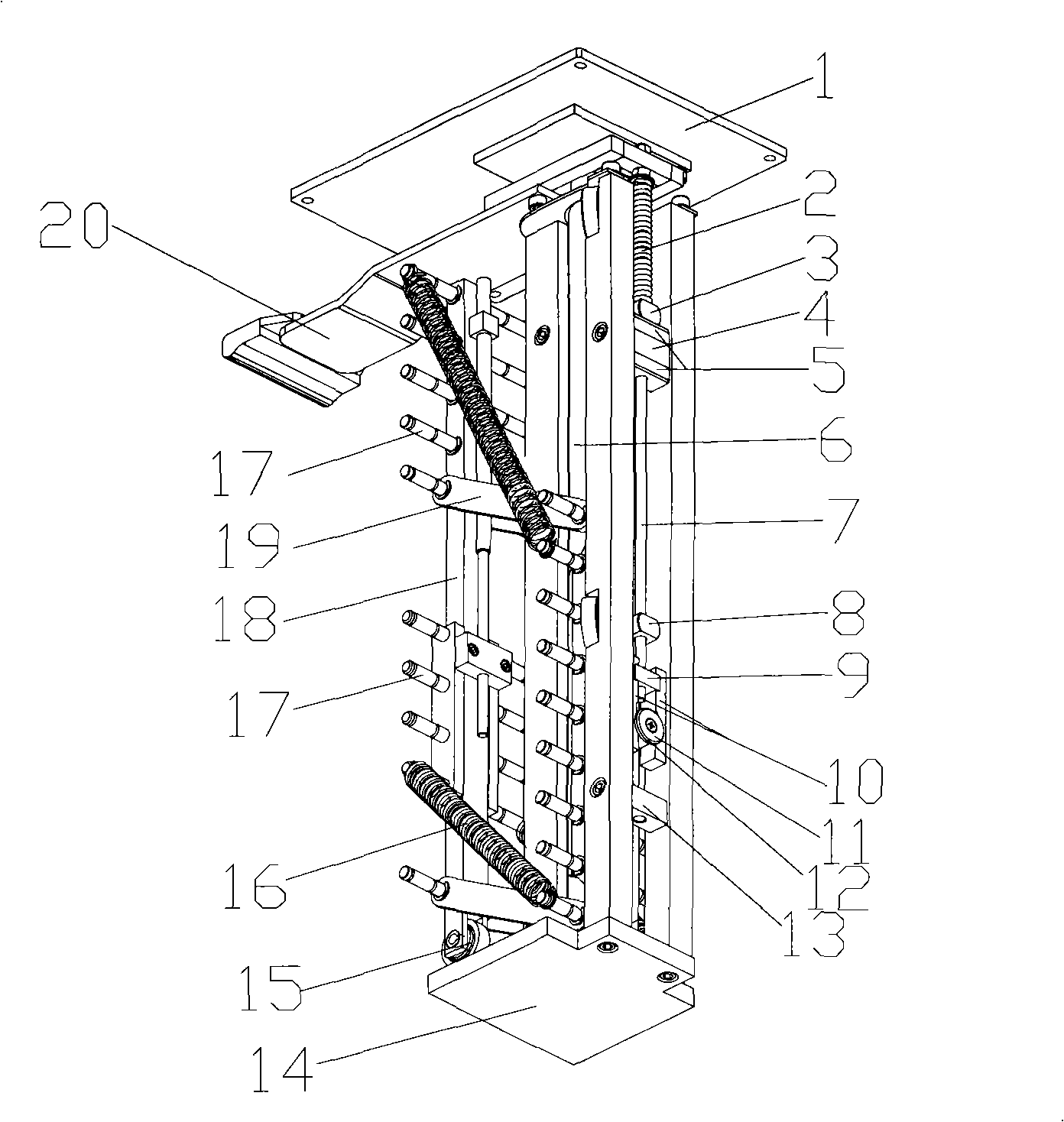
[0025] like Figure 1-7 Shown: 1 is the end panel, 2 is the locking spring, 3 is the upper positioning block, 4 is the upper block, 5 is the buffer plate, 6 is the lifting column, 7 is the locking round rod, 8 is the lower positioning block, 9 10 is the locking piece, 11 is the locking limit piece, 12 is the locking ring, 13 is the lower block, 14 is the support base, 15 is the bearing, 16 is the spring, 17 is the spring hanger Rod, 18 is a deformation support column, 19 is a connecting rod, 20 is a handle, 21 is a rear support column, 22 is a front support column, 23 is a rolling rail, 24 is a fixed bolt, 25 is a threaded screw mandrel, and 26 is a connecting block. The 27th is a lift regulating seat, the 28th is a table top, the 29th is a lifting structure, the 30th is a base, the 31st is a shell, and the 32nd is a locking bolt.

[0026] The stepless mechanical lifting device of the present invention includes a table top 28, a lifting structure 29 and a base 30, the lifting...


PUM


Abstract

The invention relates to a mechanical workbench, the manual stepless lifting of which can be realized under very small force. The mechanical worktable comprises a table top, a lifting structure and a base. The lifting structure is arranged between the table top and the base. A front supporting column and two rear supporting columns are fixedly arranged on the base. A handle is arranged on the lower bottom surface of the table top. A lifting column is arranged between the two rear supporting columns and the front supporting column and is connected with the handle. A deformed supporting column is arranged on the other side of the front supporting column. The lifting column and the deformed supporting column are provided with transverse spring hanging rods. The spring hanging rods of the lifting column and the spring hanging rods of the deformed supporting column can be connected together through connecting rods, and after connection, the connecting rods, the lifting column and the deformed supporting column form a parallelogram.

Description

technical field [0001] The invention belongs to a lifting device, in particular to a mechanical workbench capable of stepless lifting. Background technique: [0002] At present, the lifting devices on the domestic market are mainly divided into three categories: electric lifting devices, mechanical lifting devices, hydraulic or pneumatic lifting devices. [0003] Both the pneumatic lifting device and the hydraulic lifting device are provided with necessary lifting device boards, scissor support frames and bases, and the scissor support frames are also provided with jack devices. Pneumatic or hydraulic lifting devices have high working stability, but they are also expensive, and must be driven by active sources, which are noisy and difficult to maintain. Especially hydraulic lifting devices are prone to oil leakage and pollute the environment. [0004] Although the structure of the electric lifting device is relatively simple, it needs to be used when there is a power supply...

Claims


Application Information

Patent Timeline
Patent Type & Authority Applications(China)
IPC IPC(8): B66F7/06
Inventor 彭显然于航陈文光
Owner SHANGHAI MEDIWORKS PRECISION INSTR CO LTD
Why Eureka
Eureka Blog
Learn More