Connecting rod structure for engines

A technology of connecting rod structure and engine, which is applied to connecting rods, connecting rod bearings, mechanical equipment, etc., can solve the problems of complex positioning, poor connecting rod rigidity, and inconvenient processing, and achieves high connecting rod strength, uniform force, and structural simple effect

Inactive Publication Date: 2010-10-20
WUXI KIPOR POWER CO LTD
View PDF0 Cites 13 Cited by
  • Summary
  • Abstract
  • Description
  • Claims
  • Application Information

AI Technical Summary

Problems solved by technology

[0002] At present, according to statistics, when the ratio of the diameter of the big end hole of the connecting rod of an in-line engine to the diameter of the cylinder is greater than 0.73, if the connecting rod with a flat cut is used, the lateral dimension of the big end of the connecting rod will be larger than the diameter of the cylinder, so that when the piston connecting rod is assembled to the engine When installing, the piston connecting rod must be installed in the cylinder liner first, and then installed together with the cylinder liner into the cylinder body. When the piston connecting rod is removed from the engine, the cylinder liner and piston connecting rod must be pulled out of the body together, so that The disassembly and assembly process of the piston connecting rod is cumbersome and complicated, and the maintenance of the whole machine is time-consuming and labor-intensive, which increases the cost
Of course, this kind of engine can also use connecting rods with oblique cuts, but the positioning of the connecting rod body and connecting rod cover with oblique cuts is complicated, the processing is inconvenient, the rigidity of the connecting rods is poor, and the manufacturing cost is relatively high.

Method used


Image

  • Connecting rod structure for engines
  • Connecting rod structure for engines
  • Connecting rod structure for engines

Examples


Embodiment Construction

[0016] The present invention will be further described below in conjunction with specific drawings and embodiments.

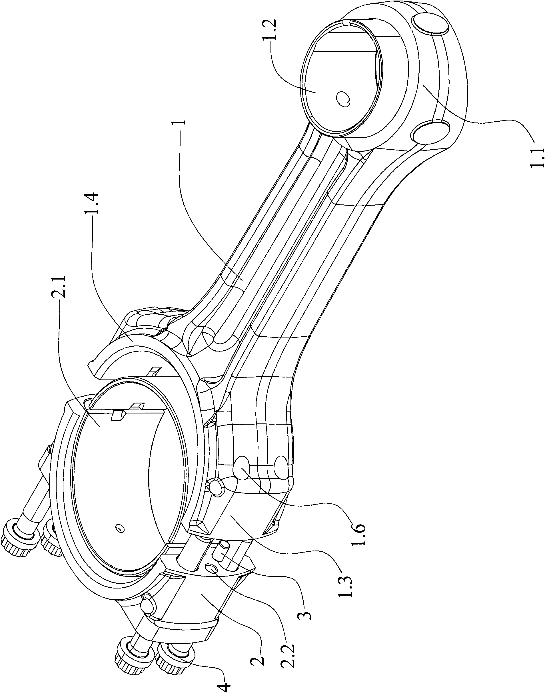
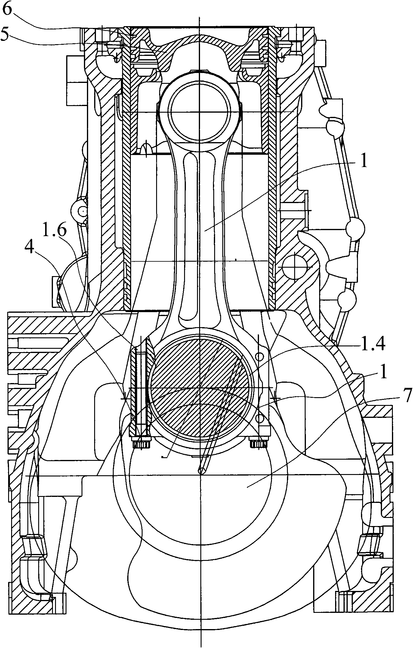
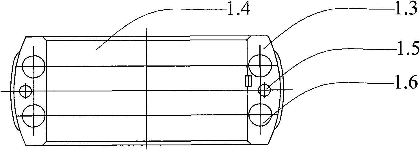
[0017] As shown in the figure, the present invention mainly consists of connecting rod body 1, connecting rod small head 1.1, connecting rod bushing 1.2, connecting rod big head 1.3, connecting rod lower tile 1.4, lower positioning pin hole 1.5, lower bolt hole 1.6, connecting rod Cover 2, connecting rod upper tile 2.1, upper positioning pin hole 2.2, upper bolt hole 2.3, positioning pin 3 and connecting rod bolt 4 and other parts constitute.

[0018] The connecting rod structure of the engine includes a connecting rod body 1 and a connecting rod cover 2, a connecting rod small end 1.1 is integrally connected to the rear end of the connecting rod body 1, and a connecting rod bushing 1.2 is arranged inside the connecting rod small end 1.1. The front end of the connecting rod body 1 is integrally connected with a connecting rod big head 1.3, a connecting rod lowe...


PUM


Abstract

The invention relates to an engine accessory, in particular to a connecting rod structure for engines. The connecting rod structure mainly comprises a connecting rod body and a connecting rod cover. The connecting rod structure is characterized in that: both the left and the right sides of the connecting rod cover are provided with two upper bolt holes, both the left and the right sides of a big connecting rod end are provided with two lower bolt holes, connecting rod bolts are correspondingly screwed in the upper bolt holes and the lower bolt holes on the same side, an upper positioning pin hole is arranged between the corresponding upper bolt holes, and a lower positioning pin hole is arranged between the corresponding lower bolt holes. Since the connecting rod body is provided with the screw holes, connecting rod bolts can be used for directly locking the connecting rod body and the connecting rod cover, so that connecting rod nuts are dispensed with, the connecting rod structure can be improved from the conventional flat-cut model, the connecting rod can be uniformly stressed, the strength of the connecting rod is higher than the strength of the connecting rod with two bolts by calculation and analysis, the development cycle is short, and machining is easy.

Description

technical field [0001] The invention relates to an engine accessory, in particular to an engine connecting rod structure. Background technique [0002] At present, according to statistics, when the ratio of the diameter of the big end hole of the connecting rod of an in-line engine to the diameter of the cylinder is greater than 0.73, if the connecting rod with a flat cut is used, the lateral dimension of the big end of the connecting rod will be larger than the diameter of the cylinder, so that when the piston connecting rod is assembled to the engine When installing, the piston connecting rod must be installed in the cylinder liner first, and then installed together with the cylinder liner into the cylinder body. When the piston connecting rod is removed from the engine, the cylinder liner and piston connecting rod must be pulled out of the body together, so that The disassembly and assembly process of the piston connecting rod is cumbersome and complicated, and the mainte...

Claims


Application Information

Patent Timeline
Patent Type & Authority Applications(China)
IPC IPC(8): F16C7/02
CPCF16C7/023F16C9/04
Inventor 肖亨琳
Owner WUXI KIPOR POWER CO LTD
Why Eureka
Try Eureka