Plastic centrifugal pump

A centrifugal pump and plastic technology, applied in the direction of pumps, pump components, non-variable-capacity pumps, etc., can solve the problems of short service life, reduce product yield, increase production costs, etc., achieve good economic benefits and energy saving, reduce Convective shock, the effect of improving efficiency

Active Publication Date: 2017-02-15
宜兴市宙斯泵业有限公司
View PDF5 Cites 1 Cited by
  • Summary
  • Abstract
  • Description
  • Claims
  • Application Information

AI Technical Summary

Problems solved by technology

[0003] The main reason why the plastic impeller affects the efficiency of the pump: the blades of the metal impeller are made of metal and have high strength, so they can be processed into thin blades with good blade shape, so the efficiency is high; while the blades of the plastic impeller are low in strength and poor in temperature resistance, so Only thicker blades can be made to improve the strength of the blades and prolong the wear life of the impeller; otherwise, if the plastic impeller is processed into the same thin blade as the metal impeller, the service life of the impeller will be shortened due to insufficient strength
like Figure 1~3 As shown, the blade 1.1 of the plastic impeller 1 is thickened, which makes the tail blade 1.1.1 at the inner arc of the impeller grow, changes the angle of the guide angle at the liquid outlet of the impeller blade, and changes the flow velocity of the liquid at the liquid outlet of the impeller Conflict with the flow direction and the flow direction of the fluid 2.1 in the pump cavity of the pump casing 2, so that the fluid in the pump volute cavity produces a spiral flow area 2.1. Increased resistance reduces pump efficiency
Therefore, it is difficult to find a solution for the best of both worlds between the thickness (strength) of the impeller of the plastic pump and the efficiency of the pump, that is, thick blades will cause low pump efficiency, and thin blades will cause short service life of the pump.
[0004] Some people in the industry also use metal embedded parts in the impeller blades to reduce the thickness of the plastic impeller blades and improve pump efficiency by increasing the steel strength of the blades. Reduce the yield of products and increase production costs. Therefore, the technology has not been widely promoted and applied for decades since the plastic pump was on the market.

Method used


Image

  • Plastic centrifugal pump
  • Plastic centrifugal pump
  • Plastic centrifugal pump

Examples


Embodiment 1

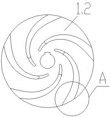
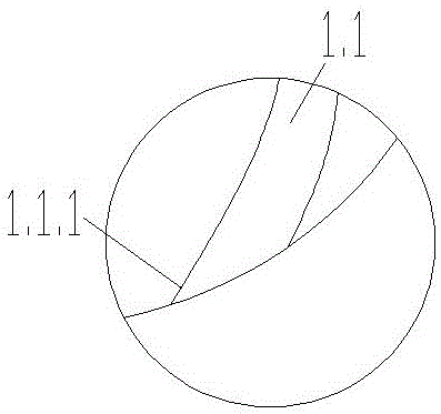
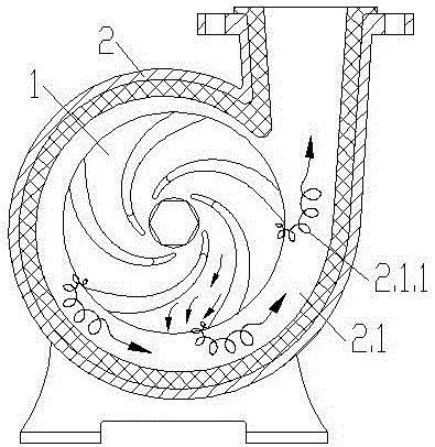
[0032] Embodiment 1: as Figure 4~7 , a plastic centrifugal pump, including a pump casing 2, a main shaft 5, a shaft seal 6 on the main shaft 5, a bearing seat 4, and an impeller 1 installed at the end of the main shaft 5 and located in the volute cavity of the pump casing 5, and the impeller 1 includes an impeller spoke The impeller blade 1.1 on the plate 1.2 and the impeller width plate 1.2, the inwardly curved side cut of the tail of the impeller blade 1.1 is provided to make the flow direction angle of the fluid thrown out of the impeller flow channel liquid outlet 1.2 larger, so that the fluid flows from the impeller flow channel liquid outlet 1.2 Inclined diversion angle 1.1.1 for forward flow towards the outlet of the pump volute flow channel. Inclined diversion angle 1.1.1 The angle E of the end point B along the tangent of the arc surface and the axis formed by the end point B and the center O of the impeller 1 is 10~40 degrees. The straight-line distance D between t...

Embodiment 2

[0040] Embodiment 2: with reference to embodiment 1, as Figure 4~12As shown, the head, flow rate, diameter and other performance parameters of the centrifugal pump can be selected arbitrarily according to the needs. Then choose ultra-high molecular weight polyethylene with a molecular weight of 5 million as raw material, and use the method of molding to make a steel-lined plastic pump casing 2, pump cover 3, and impeller 1, and then cut and process the diversion angle at the tail of the blade 1.1 of the impeller 1. 1.1.1, each part is trimmed and deburred, and then assembled with the processed main shaft, shaft seal, bearing seat and other pump components in a conventional way, and then assembled with the motor and base to form a plastic centrifugal pump. After debugging, painting , packaging and other processes, you can get an improved plastic centrifugal pump whose efficiency is about 2~4% higher than that of conventional plastic centrifugal pumps.

[0041] The impeller se...

Embodiment 3

[0043] Embodiment 3: Referring to Embodiment 2, ceramics and silicon carbide can be selected as the flow-through material of the impeller, the pump casing, and the pump cover.


PUM


Abstract

The invention discloses a plastic centrifugal pump. The plastic centrifugal pump comprises a pump shell, a main shaft, a shaft seal on the main shaft, a bearing base, and an impeller mounted at the end part of the main shaft and positioned in a volute cavity of the pump shell; the impeller includes an impeller spoke plate, and an impeller blade on the impeller spoke plate; and the inner bending side incision of the tail part of the impeller blade is provided with an inclined guide angle for increasing the flowing angle of a fluid thrown out from a liquid outlet of an impeller runner to forwards flow the fluid in the direction of the liquid outlet of the impeller runner. The thickness and the intensity of the plastic impeller blade are not changed, and the form of the tail part of the impeller blade is only changed, so that the moving direction of the fluid is changed, the generation or / and increment of an eddy current area, a reverse current area and a slow flowing area in a pump cavity is reduced, the convection impact of the fluid is reduced, and the efficiency of the pump is promoted.

Description

technical field [0001] The invention relates to the improvement of a plastic centrifugal pump, which belongs to the machinery industry by improving the efficiency of the lifting pump by about 2-4%. Background technique [0002] Plastic centrifugal slurry pump is a pump widely used in chemical industry, environmental protection, smelting, electric power, non-metallic mineral processing and other industrial fields to transport slurry. It has the advantages of good chemical resistance and anti-corrosion, especially ultra-high molecular weight polymer Centrifugal pumps made of vinyl also have excellent wear resistance, so they can be used to transport corrosive and abrasive slurry, ore slurry, etc. Moreover, the national consumption is huge. It is conservatively estimated that there are about 2 million units in operation, and the annual market sales are nearly 200,000 units. Although the centrifugal pump made of ultra-high molecular weight polyethylene has excellent corrosion r...

Claims


Application Information

Patent Timeline
Patent Type & Authority Applications(China)
IPC IPC(8): F04D29/22F04D29/24F04D29/02
CPCF04D29/026F04D29/2227F04D29/242
Inventor 蒋龙福蒋凌超
Owner 宜兴市宙斯泵业有限公司
Why Eureka
Try Eureka