
Horizontal-type bushing-type high temperature exhaust-heat recovery unit capable of generating saturated vapor and superheated vapor at the same time

A technology of waste heat recovery device and superheated steam, which is applied in the direction of steam superheating, steam generation, lighting and heating equipment, etc., which can solve the problems of high manufacturing cost and difficulty, high material requirements for connecting pipelines and recovery devices, and achieve easy material acquisition and low cost , the effect of reducing the difficulty of manufacturing

Active Publication Date: 2012-01-11
NANJING GOODCHINA CHEM TECH
View PDF0 Cites 0 Cited by
  • Summary
  • Abstract
  • Description
  • Claims
  • Application Information

AI Technical Summary

Problems solved by technology

[0004] The purpose of the present invention is to design a energy-saving and easy-to-manufacture energy-saving device that can mostly be manufactured with ordinary materials, aiming at the problems of high material requirements for connecting pipes and recovery devices in existing waste heat recovery devices, and high manufacturing cost and difficulty. A horizontal sleeve-type high-temperature waste heat recovery device that simultaneously generates saturated steam and superheated steam

Method used


Image

  • Horizontal-type bushing-type high temperature exhaust-heat recovery unit capable of generating saturated vapor and superheated vapor at the same time
  • Horizontal-type bushing-type high temperature exhaust-heat recovery unit capable of generating saturated vapor and superheated vapor at the same time
  • Horizontal-type bushing-type high temperature exhaust-heat recovery unit capable of generating saturated vapor and superheated vapor at the same time

Examples


Embodiment Construction

[0030] The following structural drawings and embodiments further illustrate the present invention.

[0031] Such as Figure 4 , Figure 5 shown.

[0032] A horizontal sleeve-type high-temperature waste heat recovery device capable of simultaneously generating saturated steam and superheated steam, including a high-temperature connecting pipe 3, a high-pressure outer header 5, a high-temperature inner header 7, a boiler outer cylinder 8 and a casing composed of The waste heat boiler tube bundle 13, the high-pressure external header 5 are connected to the reactor 1 through the connecting flange 4, the high-temperature internal header 7 is installed in the high-pressure external header 5, and the inlet end of the high-temperature internal header 7 is connected to one end of the high-temperature connecting pipe 3 The other end of the high-temperature connecting pipe 3 extends into the reactor 1; the heat exchange part of the waste heat boiler tube bundle 13 is installed in the b...


PUM


Abstract

The invention discloses a horizontal-type bushing-type high temperature exhaust-heat recovery unit capable of generating saturated vapor and superheated vapor at the same time, which comprises a high-temperature connection pipe (3), a high-pressure external header (5), a high- temperature internal header (7), a boiler outer barrel body (8) and an exhaust-heat boiler tube bank (13) composed of bushings, and is characterized in that the bushing is composed of a heat isolation pipe (10), an inner bushing (11) and an outer bushing (12); the boiler outer barrel body (8) is provided with a clapboard (15); a communicated clapboard (15) is arranged on the boiler outer barrel body (8); the saturated vapor at a saturated vapor generation area is introduced into a superheated vapor generation area and a superheated vapor generation segment (16) of the exhaust-heat boiler tube bank (13) for exchanging heat to generate a saturated vapor connection pipe (18) of superheated vapor; a superheated vapor outlet pipe and a saturated vapor outlet pipe are arranged on the boiler outer barrel body (8); and meanwhile, the difficult problem difficult to be realized in the past that the medium-pressure or high- pressure saturated vapor and the superheated vapor can be generated at the same time in one exhaust-heat recovery unit.

Description

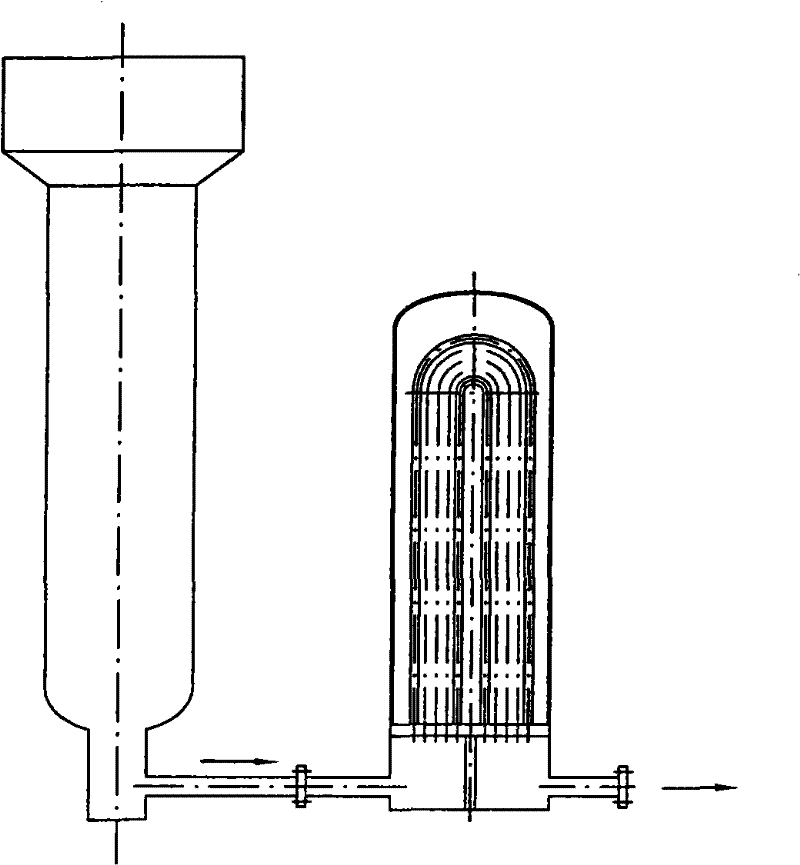
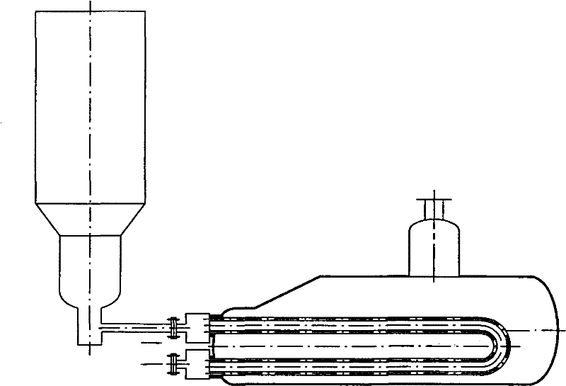
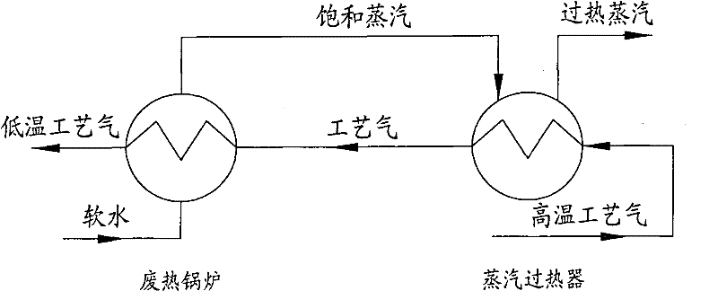
technical field [0001] The invention relates to a waste heat recovery device, in particular to a waste heat recovery device for a chemical reactor, in particular to a waste heat recovery device which has low material requirements, low manufacturing cost and can directly by-produce saturated steam and superheated steam in one device Horizontal triple casing high temperature waste heat recovery device. Background technique [0002] ①At present, the waste heat recovery device after the reactor is usually completed by connecting the high-temperature gas to the waste heat recovery device (waste heat boiler or water heater) through the outlet pipe. For the traditional structure, see figure 1 , figure 2 , under the conditions of higher pressure, higher temperature and corrosive media, the design and manufacture of this waste heat recovery device connected by pipelines are very difficult (for example, the gas temperature of the ammonia synthesis reactor is 450 °C, The pressure is...

Claims


Application Information

Patent Timeline
Patent Type & Authority Patents(China)
IPC IPC(8): F22B1/18F22G1/14
Inventor 吕仲明
Owner NANJING GOODCHINA CHEM TECH
Learn More