Device for testing push-pull force of electromagnet

A push-pull force test, electromagnet technology, applied in the direction of measuring devices, force/torque/power measuring instruments, instruments, etc., can solve the problems of low measurement accuracy and work reliability, long measurement time, unsafe operation, etc.

Inactive Publication Date: 2010-10-20
XIANGTAN UNIV
View PDF0 Cites 32 Cited by
  • Summary
  • Abstract
  • Description
  • Claims
  • Application Information

AI Technical Summary

Problems solved by technology

The operation of this method is unsafe, the measurement time is long, the efficiency is low, and an external displacem

Method used


Image

  • Device for testing push-pull force of electromagnet
  • Device for testing push-pull force of electromagnet
  • Device for testing push-pull force of electromagnet

Examples


Embodiment Construction

[0032] The present invention will be further described below in conjunction with the accompanying drawings.

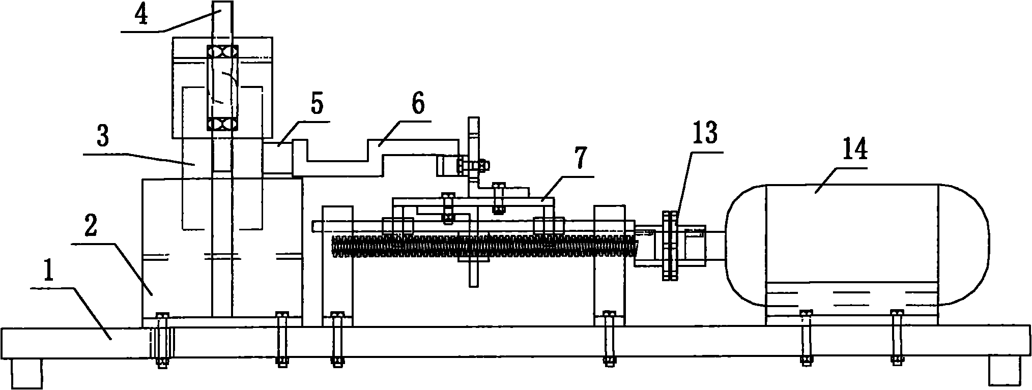
[0033] figure 1 Shown is a schematic diagram of the electromagnet push-pull force test setup. The electromagnet push-pull force testing device is composed of a force sensor 6, a displacement feed and retreat device 7, a test bench 1, a V-shaped block 2, a pressing device 4, a stepping motor 14 and an attachment for connection or fixing.

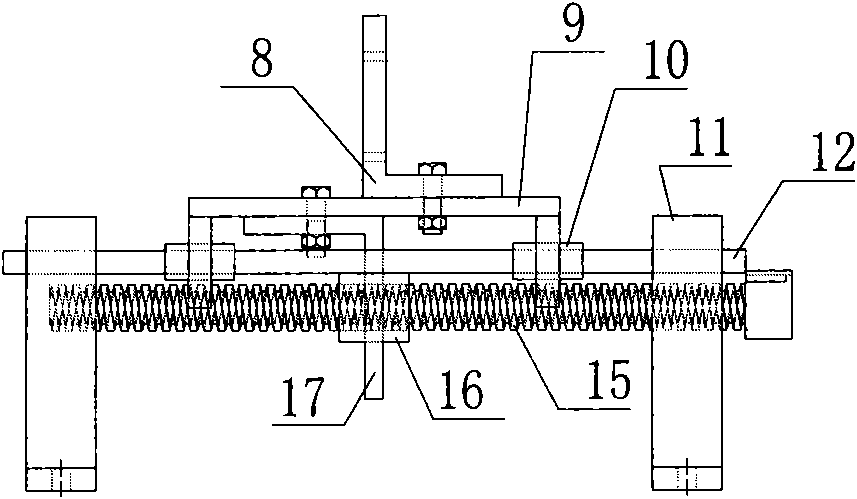
[0034] There is a concave T-shaped slot on the V-shaped block 2, and a convex T-shaped slot on the test bench 1. The V-shaped block 2 and the test bench 1 are connected together through the T-shaped slot, and the tested electromagnet 3 is placed on V On the type block 2, it is pressed by the pressing device 4. The armature 5 of the electromagnet is in contact with the left end of the force sensor 6 . The right end of the force sensor 6 is connected with the displacement feeding and retreating device 7 , and the displacement feeding...


PUM


Abstract

The invention provides a device for testing push-pull force of an electromagnet, which comprises a force sensor, a displacement feeding and backing device, a testing bench, a V-shaped block, a compression device, a stepper motor, connecting or fixing accessories and the like. The force sensor is used for measuring electromagnetic force generated by the electromagnet in different positions or under different currents; the displacement feeding and backing device is used for controlling the stroke of the armature of the electromagnet or fixing the armature in the required position; the testing bench is used for mounting the V-shaped block, the displacement feeding and backing device, the stepper motor and the like; the V-shaped block is used for mounting electromagnets with different sizes and different shapes; the compression device is used for compressing electromagnets with different heights; the stepper motor is used for controlling the displacement of the displacement feeding and backing device; and the connecting or fixing accessories are used for connecting or fixing and adjusting other components.

Description

technical field [0001] The present invention relates to a device for testing the push-pull force of an electromagnet, more specifically to a device capable of testing the push-pull force of an electromagnet and obtaining the relationship between the electromagnetic force and the stroke (displacement) of the armature and the relationship between the electromagnetic force and the general A test device for the relationship between input currents. Background technique [0002] As a kind of electric-machine converter, electromagnet is more and more used in metallurgy, mining, machinery, transportation, etc. widely. The electromagnetic force and armature stroke of the electromagnet are its main performance indicators, and also the main basis for the selection of the electromagnet, so it is very necessary to test its force characteristics. [0003] At present, there are mainly two methods for measuring the force characteristics of electromagnets. One is to measure it by loading ...

Claims


Application Information

Patent Timeline
IPC IPC(8): G01L5/00
Inventor 谭志飞毛美姣黄辉先
Owner XIANGTAN UNIV
Why Eureka
Try Eureka