
Three-dimensional focal imaging method of look-down array antenna synthetic aperture radar

A technology of synthetic aperture radar and array antenna, which is used in the reflection/re-radiation of radio waves, the use of re-radiation, radio wave measurement systems, etc. Distance migration corrects problems such as low operational efficiency of ground distance compression, reducing time and enhancing universality.

Inactive Publication Date: 2010-10-20
INST OF ELECTRONICS CHINESE ACAD OF SCI
View PDF0 Cites 16 Cited by
  • Summary
  • Abstract
  • Description
  • Claims
  • Application Information

AI Technical Summary

Problems solved by technology

[0006] The purpose of the present invention is to provide a three-dimensional focusing imaging method for down-looking array antenna synthetic aperture radar, which considers the two-dimensional range migration correction, improves the compression efficiency of ground distance and relaxes the requirement of ground distance sampling interval at the same time, It solves the problem that the existing three-dimensional focusing imaging method does not perform range migration correction, the low efficiency of ground range compression calculation, and the requirement of too small ground range sampling interval of down-looking array antenna synthetic aperture radar, which is not conducive to practical application.

Method used


Image

  • Three-dimensional focal imaging method of look-down array antenna synthetic aperture radar
  • Three-dimensional focal imaging method of look-down array antenna synthetic aperture radar
  • Three-dimensional focal imaging method of look-down array antenna synthetic aperture radar

Examples


Embodiment Construction

[0039] Various details involved in the technical solution of the present invention will be described in detail below in conjunction with the accompanying drawings. It should be pointed out that the described embodiments are only intended to facilitate the understanding of the present invention, rather than limiting it in any way.

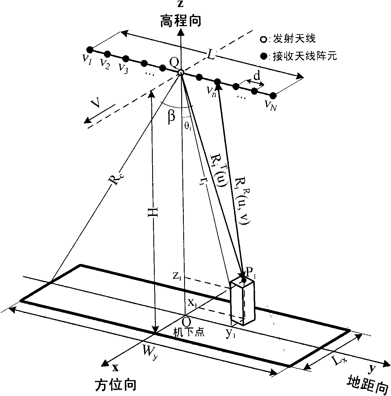
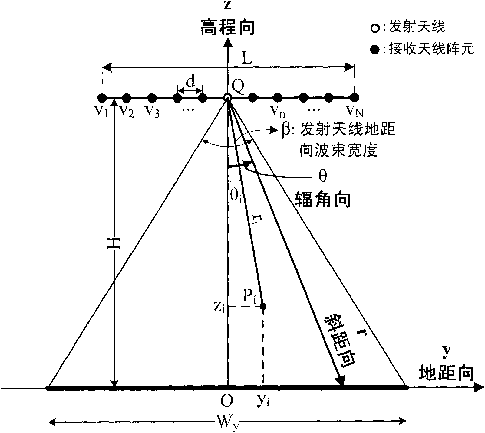
[0040] Such as figure 1 As shown, Oxyz is the spatial Cartesian coordinate system where the downward-looking array antenna SAR and its imaging area are located. The imaging area is located in the area directly below the flight path of the downward-looking array antenna SAR, and about the flight track, that is, the x-axis direction Symmetry, P i (x i ,y i ,z i ) is the i-th point target in the imaging area and its rectangular coordinates. Qxrθ is the cylindrical coordinate system where the downward-looking array antenna synthetic aperture radar and its imaging area are located, perpendicular to the azimuth direction, that is, the ground-elevatio...


PUM


Abstract

The invention discloses a three-dimensional focal imaging method of a look-down array antenna synthetic aperture radar, which relates to radar technology. The method comprises: A) performing slant-range compression of collected original echo data of the look-down array antenna synthetic aperture radar; B) performing azimuth range migration correction of a signal obtained by the step A); C) performing the azimuth compression of a signal obtained by the step B); E) performing the ground-range range migration correction of the signal which is subjected to slant-range compression and azimuth compression; and F) performing the ground-range slant removal and ground-range Fourier transform of the signal obtained by the step E), and reestablishing the three-dimensional radar image of an imaged area in a cylindrical coordinate system. In the method of the invention, fewer antenna array elements are used for reestablishing the three-dimensional radar image of the imaged area, the range migration correction problem, which is not solved in the conventional three-dimensional imaging method, is solved, the ground-range wave beam forming calculation performed in the conventional three-dimension imaging method is converted into one time of complex multiplication and the Fourier transform, and a three-dimensional resolution image is thus acquired, and the required imaging time is reduced.

Description

technical field [0001] The invention relates to the technical field of information acquisition and processing of synthetic aperture radar, in particular to a three-dimensional focusing imaging method for downward-looking array antenna synthetic aperture radar, which can acquire a three-dimensional radar image of an imaging area directly below a carrier. Background technique [0002] Downward-looking array antenna synthetic aperture radar is a new three-dimensional imaging technology of synthetic aperture radar, such as figure 1 shown. Among them, Oxyz is the space Cartesian coordinate system where the down-looking array antenna SAR and its imaging area are located, P i (x i ,y i ,z i ) is the i-th point target in the imaging area and its rectangular coordinates. Qxrθ is the cylindrical coordinate system (azimuth direction, slant range direction and argument direction) where the downward-looking array antenna SAR and its imaging area are located, such as figure 2 As sh...

Claims


Application Information

Patent Timeline
IPC IPC(8): G01S13/90
Inventor 洪文杜磊王彦平吴一戎
Owner INST OF ELECTRONICS CHINESE ACAD OF SCI
Learn More