Imaging apparatus and subject tracking method
A technology for a camera device and an object area, which is applied in the field of camera device and object tracking, can solve the problems of increased computational complexity, inability to track objects, and inability to match object blocks, and achieve good detection results.
- Summary
- Abstract
- Description
- Claims
- Application Information
AI Technical Summary
Problems solved by technology
Method used
Image

Examples
Embodiment Construction
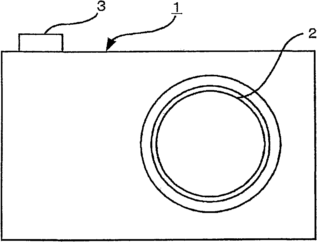
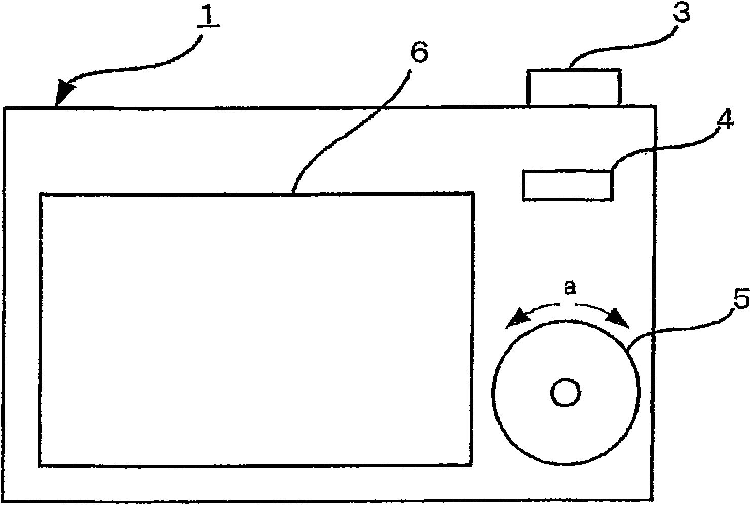
[0017] An imaging device according to an embodiment of the present invention will be described with reference to the drawings. FIG. 1(A) is a front view showing the appearance of the imaging device 1 according to this embodiment, and FIG. 1(B) is a rear view. In this imaging device 1 , an imaging lens 2 is provided on the front surface, and a shutter key 3 is provided on the top surface. The shutter key 3 includes a so-called half-shutter function capable of half-press and full-press operations. In addition, function keys 4, cursor keys 5, and a display unit 6 are provided on the back. The cursor key 5 functions as a dial switch rotatable in the direction of a in FIG. 1(B). The display unit 6 is composed of, for example, an LCD (Liquid Crystal Display) having an aspect ratio of 16:9.
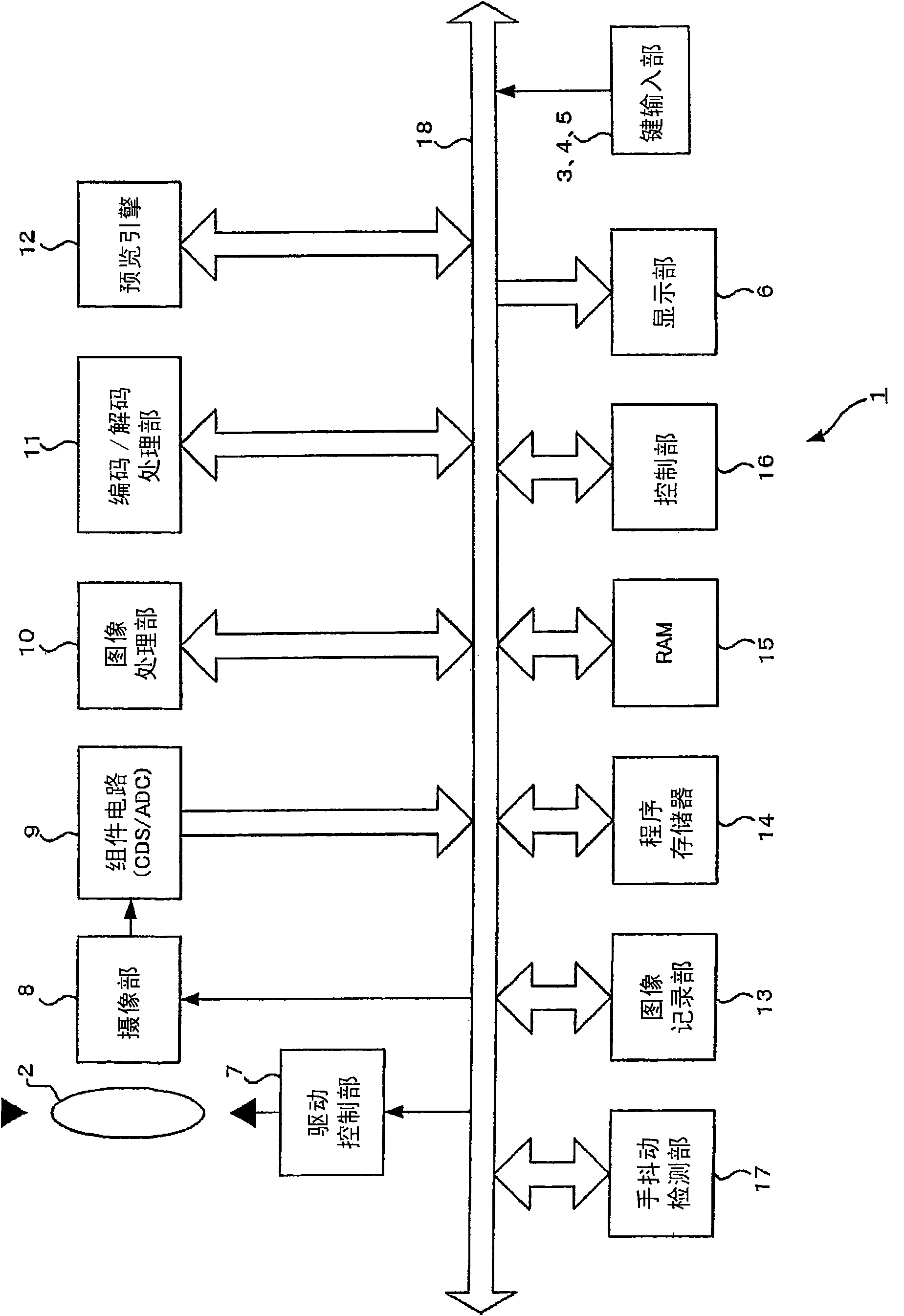
[0018] figure 2 It is a block diagram showing the basic configuration of the imaging device 1 . The imaging device 1 is composed of an imaging lens 2, key input units 3-5, a display unit 6,...
PUM
 Abstract
Description
Claims
Application Information
 - Generate Ideas
- Intellectual Property
- Life Sciences
- Materials
- Tech Scout
- Unparalleled Data Quality
- Higher Quality Content
- 60% Fewer Hallucinations
Browse by: Latest US Patents, China's latest patents, Technical Efficacy Thesaurus, Application Domain, Technology Topic, Popular Technical Reports.
© 2025 PatSnap. All rights reserved.Legal|Privacy policy|Modern Slavery Act Transparency Statement|Sitemap|About US| Contact US: help@patsnap.com