Hydraulic control device for lockup clutch

A lock-up clutch, oil pressure control technology, applied in transmission, transmission control, fluid transmission, etc., can solve the problems of bubble retention, vehicle driving performance damage, insufficient transmission torque, etc., to restrain transmission Reduced torque and improved drive performance

Inactive Publication Date: 2010-10-20
TOYOTA JIDOSHA KK
View PDF1 Cites 8 Cited by
  • Summary
  • Abstract
  • Description
  • Claims
  • Application Information

AI Technical Summary

Problems solved by technology

[0010] The present invention is made against the background of the above-mentioned situation, and its purpose is to improve the driving performance of the vehicle due to the fact that the air bubbles remain and accumulate in the fluid transmission device when the vehicle is stopped at low oil temperature, and sufficient transmission torque cannot be obtained when starting. Damaged situation

Method used


Image

  • Hydraulic control device for lockup clutch
  • Hydraulic control device for lockup clutch
  • Hydraulic control device for lockup clutch

Examples


Embodiment Construction

[0043] Embodiments of the present invention will be described in detail below with reference to the drawings.

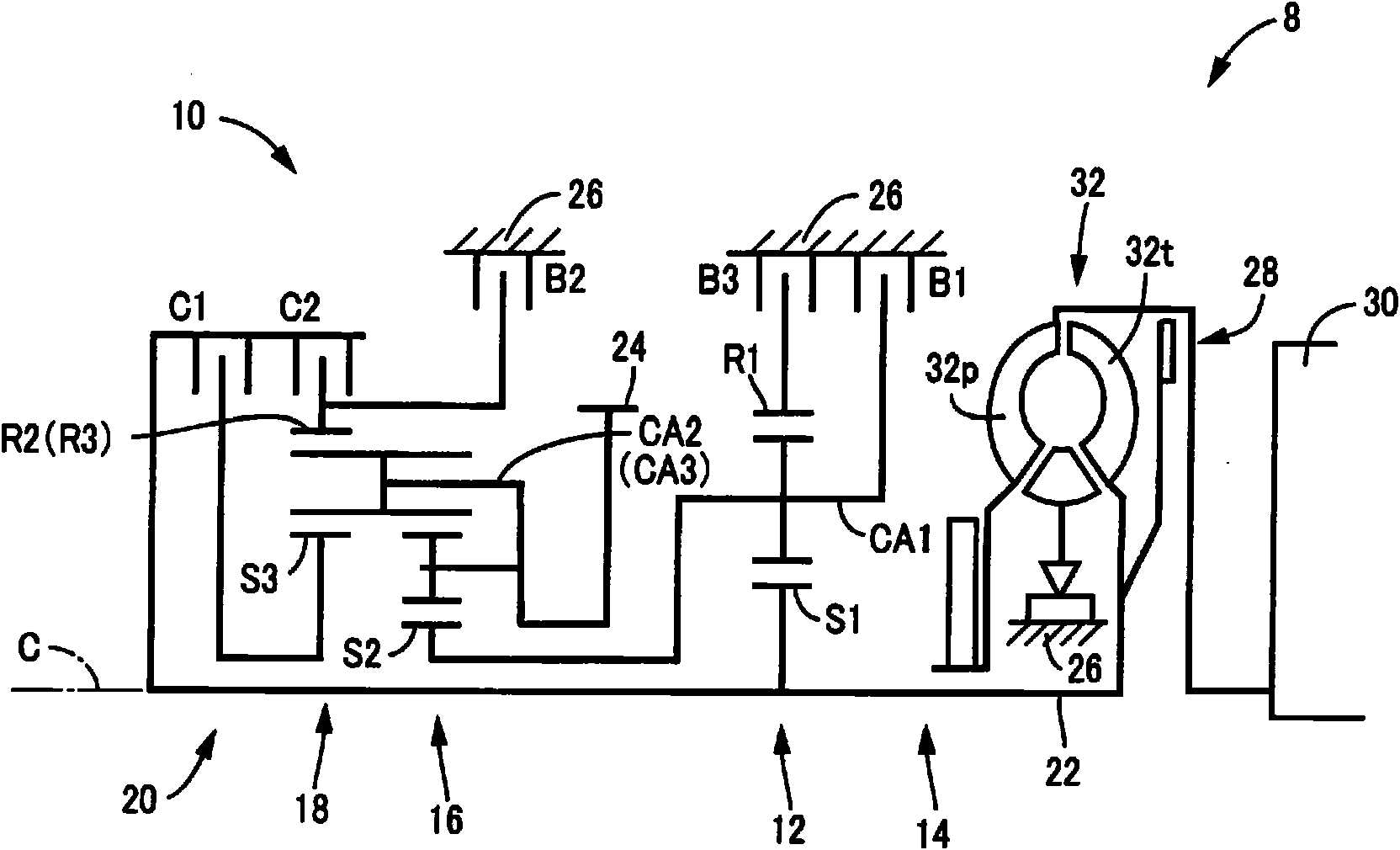
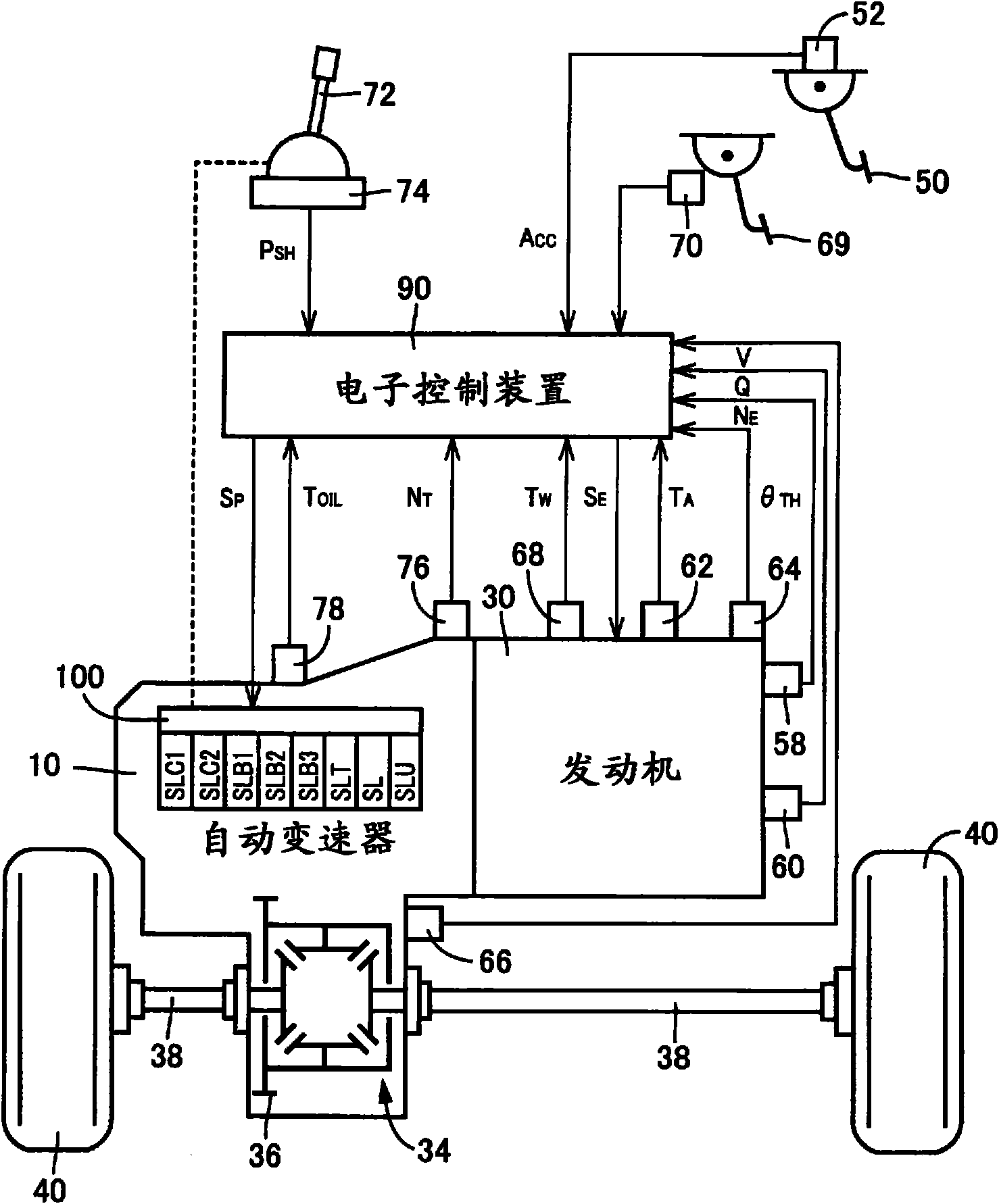
[0044] figure 1 It is a configuration diagram illustrating a schematic configuration of a vehicle transmission 8 to which the present invention is preferably applied. The vehicle transmission 8 is preferably used in an FF vehicle mounted in the left-right direction (horizontal position) of the vehicle, and the output of the engine 30 is transmitted from the torque converter 32 and the automatic transmission 10 through image 3 The illustrated differential gear unit 34 and a pair of axle shafts 38 transmit to a pair of drive wheels 40 . The engine 30 is a driving force source and is composed of an internal combustion engine such as a gasoline engine or a diesel engine. Furthermore, the torque converter 32 is a fluid transmission device that has a lock-up clutch 28 that connects a pump impeller blade 32p and a turbine blade 32t integrally or in a predetermined relat...


PUM


Abstract

A hydraulic control device for a lockup clutch prevents stagnation and accumulation of air bubbles in a torque converter when a vehicle is at a stop at low oil temperature, preventing impairment of vehicle drive performance caused by insufficient transmission torque at the time of start of the vehicle. It occurs sometimes that air-mixed hydraulic oil is supplied into a torque converter (32) from a second oil path (132) when a vehicle is at a stop, with a transmission set to a drive range such as a D range, at a low oil temperature in a time, for example, immediately after an engine (30) is started. In such a case, when a lockup clutch is disengaged, in which a second line hydraulic pressure (PL2) is supplied from the second oil path (132) to the lockup clutch (28), a third oil path (134) is interrupted (closed) to prohibit discharge of the hydraulic oil. As a result, despite large pipe path resistance due to high viscosity, the hydraulic oil in the torque converter (32) is reliably discharged from a first oil path (130) to an oil cooler (142) via a cooler oil path (140). Thus, air bubbles in the torque converter (32) are reduced with the discharge of the hydraulic oil.

Description

technical field [0001] The present invention relates to an oil pressure control device for a lock-up clutch, in particular to a technique for improving the driving performance of a vehicle which is damaged by air mixing to reduce the transmission torque of a fluid transmission device at low oil temperature. Background technique [0002] One type of hydraulic control device for a lock-up clutch includes a device including a lock-up clutch, a first oil passage, a second oil passage, and a third oil passage. Among them, the lock-up clutch is provided in a fluid transmission device such as a torque converter or a fluid coupling, and is engaged and disengaged by hydraulic pressure. The first oil passage communicates with an engagement-side oil chamber of the lock-up clutch, and supplies engagement oil pressure to the engagement-side oil chamber when the lock-up clutch is engaged. The second oil passage communicates with a disengagement-side oil chamber of the lock-up clutch, and...

Claims


Application Information

Patent Timeline
Patent Type & Authority Applications(China)
IPC IPC(8): F16H61/14
CPCF16H61/143F16H61/0206F16H59/72
Inventor 石和田健中村和明
Owner TOYOTA JIDOSHA KK
Why Eureka
Try Eureka