Image processing method for time lapse image, image processing program, and image processing device
一种图像处理装置、图像处理的技术,应用在图像数据处理、图像数据处理、图像增强等方向,达到提高精度的效果
- Summary
- Abstract
- Description
- Claims
- Application Information
AI Technical Summary
Problems solved by technology
Method used
Image


Examples
no. 1 Embodiment approach
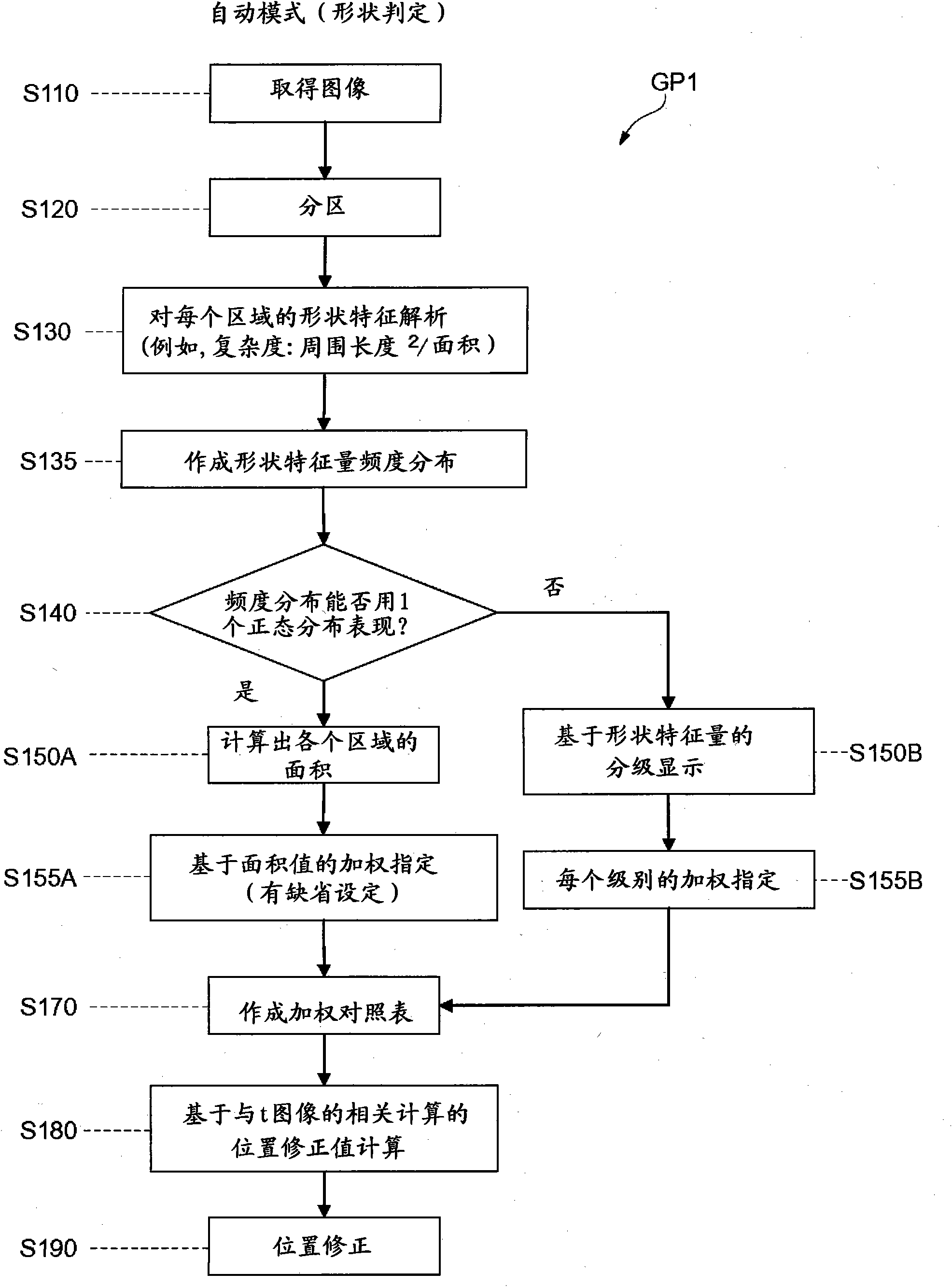
[0050] The image processing device 101 of the first embodiment is configured such that the CPU 61 executes the image processing program GP1 of the first embodiment. This image processing device 101 uses a correlation function weighted according to the feature quantity based on the feature quantity based on the object shape as the image feature quantity of the object included in the first image and the second image to perform a positional deviation calculation. Position fixes.
[0051] In the image processing program GP1, first, in step S110, the first image at time t and the second image at time t+1 recorded in RAM 63 are read and acquired, and in step S120, each area is partitioned . Various known methods can be used for partitioning, for example, binarization based on luminance values, binarization based on dispersion values, dynamic contour extraction methods such as Snakes and LevelSet methods, and the like.
[0052] Then, in step S130 , an analysis is performed based on...
no. 2 Embodiment approach
[0063] Next, the image processing device 102 of the second embodiment will be described. The image processing device 102 of the present embodiment uses, as the image feature value of the object, the feature value of the texture structure of the object within the field of view as a reference. That is, the device configuration of the image control device as a hardware resource is the same as that of the image processing device 101 of the first embodiment, but the image feature value to be judged during image processing is different from that of the image processing device 101 of the first embodiment. . Figure 7 A flow chart of the image processing program GP2 constituting the image processing device 102 read and executed by the CPU 61 is shown. Next, the image processing method of the present embodiment will be described using the processing flow of the image processing program GP2.
[0064] In the image processing program GP2, first, in step S210, the first image at time t an...
no. 3 Embodiment approach
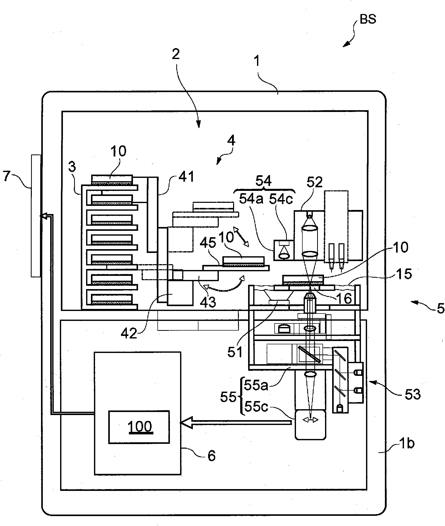
[0073] Next, the image processing device 103 of the third embodiment will be described. The image processing device 103, such as Figure 5 As shown by the dotted line in the figure, on the basis of the image processing devices 101 and 102 in the above-mentioned embodiments, a storage unit 140 for storing various feature values for image feature values, and a feature value storage unit 140 for selecting The mode selection switch 150 for a given feature quantity type is configured so that the position correction value calculation unit 120 can calculate the position correction value using a correlation function based on the weighting of the feature quantity selected by the mode selection switch 150 .
[0074] Figure 8 A flowchart is shown of the image processing program GP3 which is read and executed by the CPU 61 and constitutes the image processing device 103 . Next, the image processing method of the present embodiment will be described based on the image processing progra...
PUM
 Abstract
Description
Claims
Application Information
 - R&D
- Intellectual Property
- Life Sciences
- Materials
- Tech Scout
- Unparalleled Data Quality
- Higher Quality Content
- 60% Fewer Hallucinations
Browse by: Latest US Patents, China's latest patents, Technical Efficacy Thesaurus, Application Domain, Technology Topic, Popular Technical Reports.
© 2025 PatSnap. All rights reserved.Legal|Privacy policy|Modern Slavery Act Transparency Statement|Sitemap|About US| Contact US: help@patsnap.com