Weighing method for determining liquid level in wellbore of gas well

A technology of liquid level position and determination method, which is applied to the determination of the liquid level depth of gas wells and the field of liquid-accumulating gas wells, can solve problems such as affecting the accuracy of calculation results, consuming manpower and material resources, and achieves simple testing, reliable principle, and accurate results. Effect

Active Publication Date: 2010-10-27
PETROCHINA CO LTD
View PDF5 Cites 10 Cited by
  • Summary
  • Abstract
  • Description
  • Claims
  • Application Information

AI Technical Summary

Problems solved by technology

If the bottom hole pressure obtained by calculation is used to calculate the wellbore liquid level position, the accuracy of the calculation result will be affected; if the bottom hole pressure is obtained through downhole testing, it will also consume a certain amount of manpower and material resources

Method used


Image

  • Weighing method for determining liquid level in wellbore of gas well
  • Weighing method for determining liquid level in wellbore of gas well
  • Weighing method for determining liquid level in wellbore of gas well

Examples


Embodiment 1

[0031] Embodiment 1: The present invention will be further described in detail by taking the method of determining the position of the wellbore liquid level of a weighing gas well once as an example.

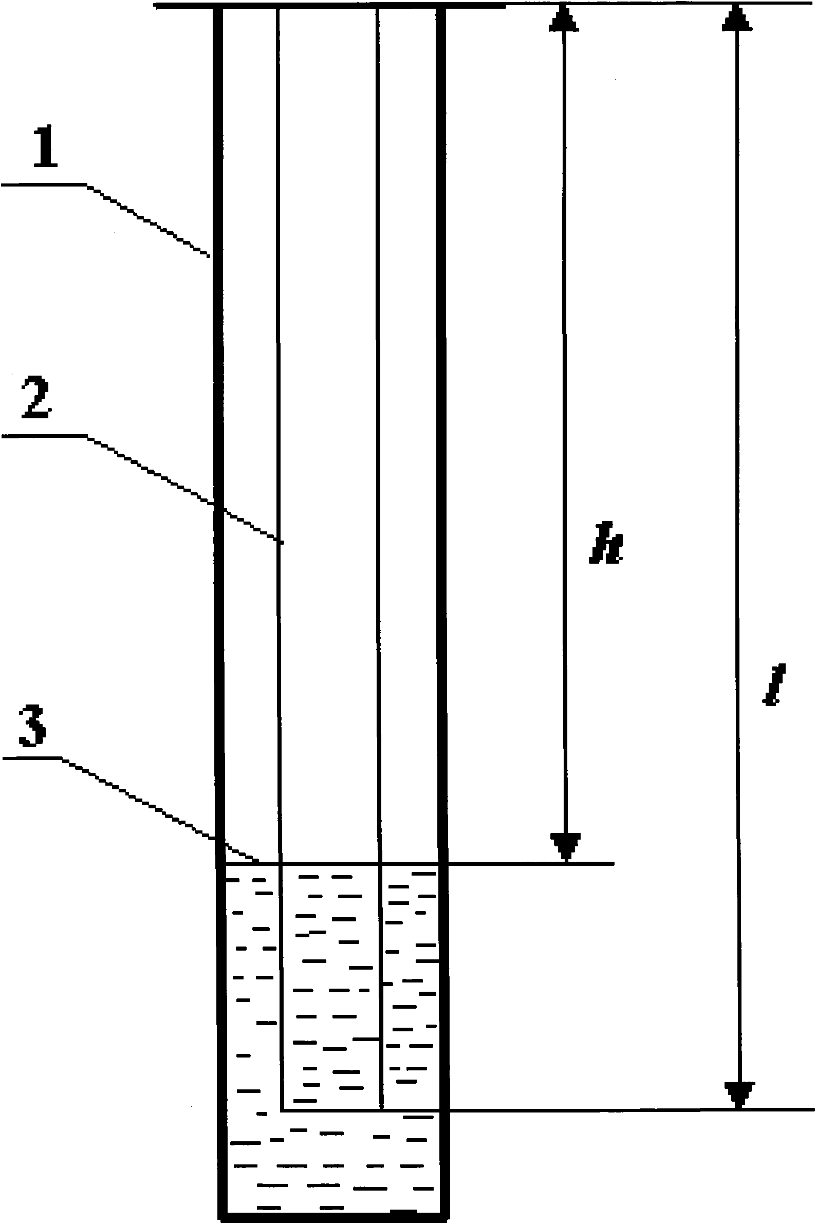
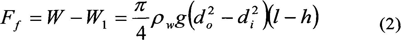
[0032] A certain gas well has a tubing string 2 in the casing 1. Tubing string 2 uses 2 7 / 8 "Thickened tubing is connected. The tubing string 2 has a length of 2200m, an outer diameter of 73mm, and an inner diameter of 62mm. The average weight of a unit tubing string 2 is 94.86N / m. The liquid density is 1010kg / m 3 , the weight of the tubing string 2 in the liquid measured at the wellhead after the gas well flooded is 204428N. Substitute the above information into the formula:

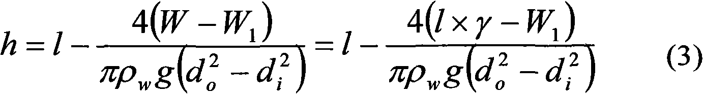
[0033] h = l - 4 ( l × γ - W 1 ) π ...

Embodiment 2

[0035] Embodiment 2: still carry out in the gas well of embodiment 1. A tubing string 2 is lowered in the casing 1 . Tubing string 2 uses 2 7 / 8 "Thickened oil pipes are connected. The length of the oil pipe string 2 is 2200m, the outer diameter is 73mm, and the inner diameter is 62mm. The average weight of the unit oil pipe string 2 is 94.86N / m. The liquid density is 1010kg / m 3 , the weight of the tubing string 2 in the liquid measured at the wellhead after the gas well is flooded is 202120N, and the above data are substituted into the formula:

[0036] h = l - 4 ( l × γ - W 1 ) π ρ w g ( d o ...

Embodiment 3

[0038] Embodiment 3: 14 times in 3 months are weighed and the distance h of the liquid level from the wellhead after the liquid accumulation in the gas well obtained by calculation is drawn into a curve corresponding to the time, and the distance h between the liquid surface and the wellhead after the liquid accumulation in the gas well is found out Elevation law. According to the liquid loading law of the gas well, it is predicted when the next liquid drainage measure of the gas well should be carried out. Those skilled in the art are familiar with gas well drainage measures and will not describe them in detail.


PUM


Abstract

The invention relates to a weighing method for determining the liquid level in the wellbore of a gas well, which is applied to the technical field of gas production in oil fields. Firstly, the length l of a tubing string going down into the gas well, the average unit length weight Gamma of the tubing string, the outer diameter do of the tubing, the inner diameter di of the tubing and the density Rho of accumulated liquid are acquired; secondly, the weighing method is utilized to weigh the weight W1 of the tubing string in the liquid at the wellhead; finally, the length l of the tubing string, the average unit length weight Gamma of the tubing string, the outer diameter do of the tubing, the inner diameter di of the tubing, the density Rho of the accumulated liquid and the weight W1 of the tubing string in the liquid are put into a formula; and after calculation, the distance h between the level of the accumulated liquid in the gas well and the wellhead is obtained. The invention is characterized in that the liquid level in the wellbore can be determined as long as the weight of the tubing string is measured at the wellhead of the gas well. Since only the weight of the tubing string in the liquid is measured at the wellhead and a testing instrument does not need to be put down into the well bottom, compared with the prior art, the method has the advantages of easy testing and more accurate result.

Description

technical field [0001] The invention relates to the field of gas field development, in particular to the determination of the depth of the wellbore liquid level of a gas well. It is a method for determining the liquid level position of the wellbore of a liquid-loaded gas well by using the weighing principle, and is suitable for a liquid-loaded gas well in which annulus of tubing and casing is connected. Background technique [0002] The presence of liquid accumulation in the wellbore of a gas well will undoubtedly affect its normal production. At the same time, the accumulation of liquid can pollute the gas layer and further reduce the productivity of the gas well. Therefore, in the process of gas well production, it is an important content of gas field dynamic monitoring to timely detect the position of the liquid level in the gas wellbore and understand the situation of liquid accumulation, and provide a basis for taking effective liquid drainage measures. At present, ther...

Claims


Application Information

Patent Timeline
Patent Type & Authority Applications(China)
IPC IPC(8): E21B47/04E21B47/047
Inventor 赵勇韩兴刚王晓荣冯朋鑫徐文龙朱李安牟春国刘静宇
Owner PETROCHINA CO LTD
Why Eureka
Try Eureka