Water-conducting and pressure-releasing type composite well wall of vertical shaft and construction method thereof

A technology of shaft wall and vertical shaft, which is applied in the directions of drainage, shaft equipment, earth-moving drilling and mining, etc., can solve the problems of large amount of shaft excavation, insignificant waterproof effect, large thickness of shaft wall structure, etc., and achieves simple structure and reduced size The effect of water pressure and convenient construction

Inactive Publication Date: 2010-10-27
SHANDONG UNIV OF SCI & TECH
View PDF5 Cites 9 Cited by
  • Summary
  • Abstract
  • Description
  • Claims
  • Application Information

AI Technical Summary

Problems solved by technology

Generally, for a shaft with a depth of 500m, the total thickness of the outer wall and the inner wall can reach 1200mm, and the thickness of the shaft wall structure is large. The resulting excavation of the shaft requires a large amount of work and a large investment, and the waterproof effect is not obvious after the construction is completed and thawed.

Method used


Image

  • Water-conducting and pressure-releasing type composite well wall of vertical shaft and construction method thereof
  • Water-conducting and pressure-releasing type composite well wall of vertical shaft and construction method thereof
  • Water-conducting and pressure-releasing type composite well wall of vertical shaft and construction method thereof

Examples


Embodiment Construction

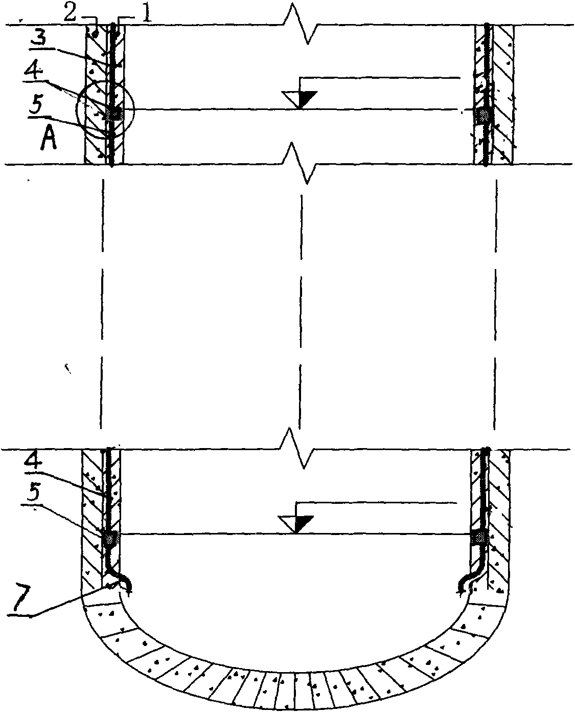
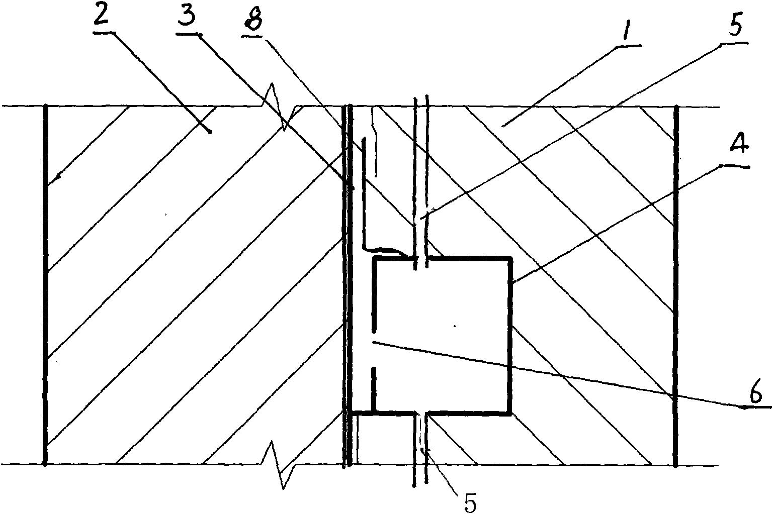
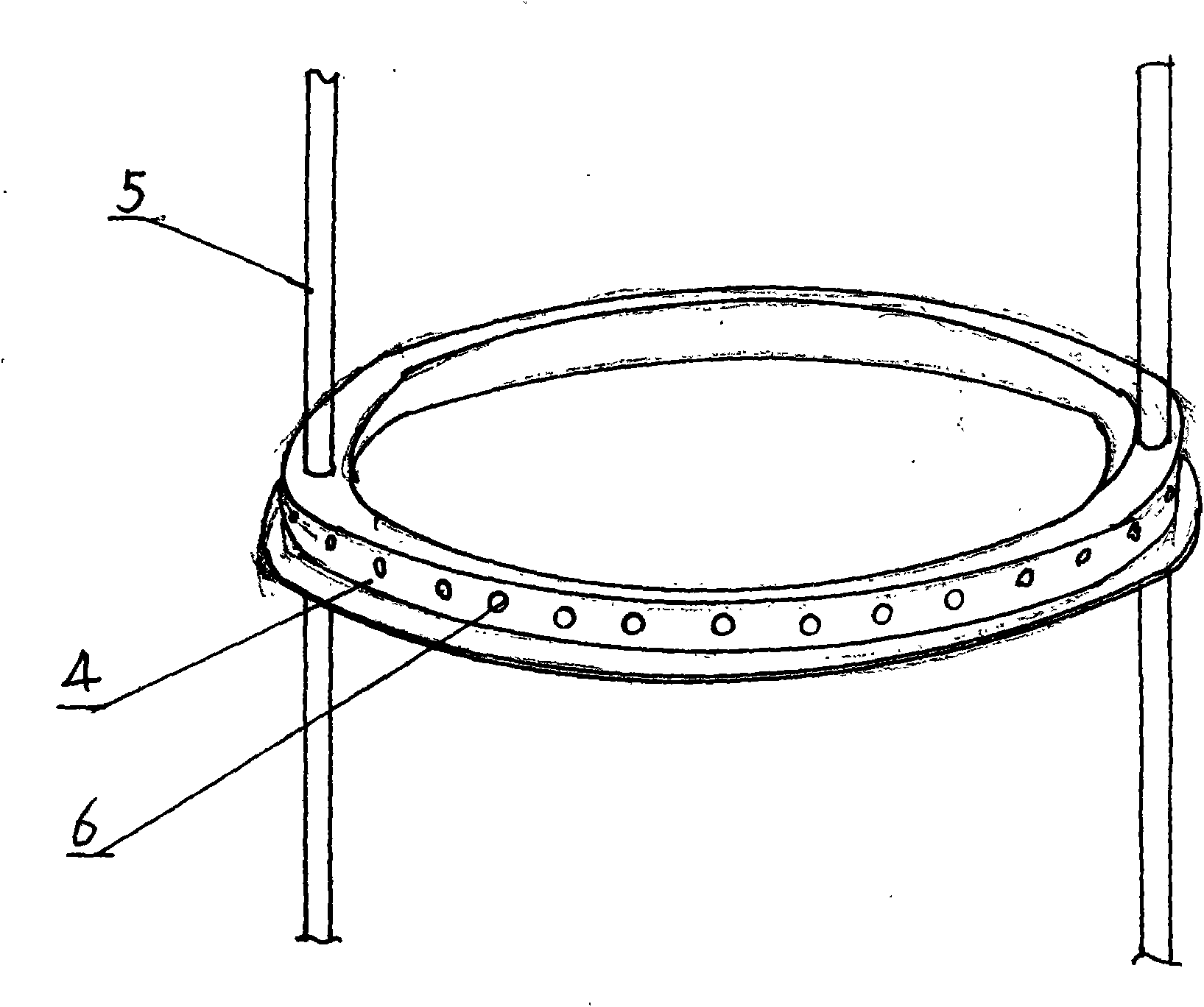
[0017] see figure 1 , figure 2 and image 3 , the present embodiment is a composite well wall composed of inner wall 1, waterproof interlayer 3 and outer wall 2, and a circle of water guide groove 4 is pre-buried on the height of each water seepage layer of inner wall 1; water guide groove 4 is a circle of closed pipes, The outer peripheral side of the pipeline is provided with a plurality of diversion holes 6; the inner cavities of all the water guide grooves 4 are communicated with the water guide pipe 5 from top to bottom, and the bottom end of the water guide pipe 5 stretches out from the bottom of the shaft after being communicated.

[0018] The inner wall of frozen sinking shaft construction is generally constructed by the bottom-up synovial membrane method or the small formwork continuous casing wall method, and the water-guiding and pressure-relieving composite shaft wall is carried out at the same time as the above-mentioned inner wall construction.

[0019] Constr...


PUM


Abstract

The invention discloses a water-conducting and pressure-releasing type composite well wall of a vertical shaft and a construction method thereof. The composite wall comprises an inner wall, a waterproof interlayer and an outer wall, wherein a circle of water-conducting groove is pre-buried in the inner wall at the height of each seepage layer; each water-conducting is a circle of enclosed pipeline, and the periphery of the pipeline is provided with a plurality of water-conducting holes; and the inner cavities of all water-conducting grooves are communicated by water-conducting pipes from top to bottom, and the bottom of each water-conducting pipe extends from the bottom of a shaft. Therefore, seepage water between the inner wall and the outer wall is conducted out. The invention has the advantages that formation water infiltrating the sandwich from the outer wall firstly flows in the water-conducting groove through the water-conducting holes and then is conducted to the bottom of the shaft through the water-conducting pipes to decrease the water head height and reduce the water pressure. Therefore, the thickness of the wall is reduced, investment is saved, and the problem of seepage caused by wall thawing after freezing sinking is solved.

Description

technical field [0001] The invention relates to a shaft wall of a vertical shaft of a mine, in particular to a shaft wall structure constructed by adopting a freezing method to sink a shaft. Background technique [0002] The shaft wall of the existing vertical shaft drilled by the freezing method is a composite shaft wall structure composed of an inner wall, a waterproof interlayer and an outer wall. This structure is used to isolate groundwater and withstand formation water and soil pressure. Generally, for a shaft with a depth of 500m, the total thickness of the outer wall and the inner wall can reach 1200mm, and the thickness of the shaft wall structure is large. The resulting excavation of the shaft requires a large amount of engineering and investment, and the waterproof effect is not obvious after the construction is completed and thawed. The research shows that most of the pressure on the shaft wall of the deep shaft is the water pressure of the formation. If the wat...

Claims


Application Information

Patent Timeline
Patent Type & Authority Applications(China)
IPC IPC(8): E21D5/00E21D5/11E21F16/00
Inventor 王渭明王磊
Owner SHANDONG UNIV OF SCI & TECH
Why Eureka
Try Eureka