Supercharge Your Innovation With Domain-Expert AI Agents!

Unpressurized serial solar energy vacuum tube heat collector

A technology of vacuum tube collectors and vacuum tubes, which is applied to solar collectors, solar collectors using working fluids, solar thermal energy, etc., can solve the problems of high energy loss, high maintenance costs, and complicated operation, and achieve the goal of manufacturing And the effect of low installation cost, reduced maintenance cost, and controllable conduction temperature

Inactive Publication Date: 2011-06-29
河北沃德沃姆新能源科技有限公司
View PDF7 Cites 0 Cited by
  • Summary
  • Abstract
  • Description
  • Claims
  • Application Information

AI Technical Summary

Problems solved by technology

When the pressure-bearing chemical medium is used to conduct heat collection, due to the serious limitation of energy loss in the transmission pipeline, the problem of long-distance conduction cannot be solved. When exchanging heat with water, due to the uncontrollable temperature of the medium, the surface of the exchanger is very short It is easy to foul in a long time, thereby reducing the conversion efficiency. At the same time, it cannot meet people's demand for instant heating of hot water in terms of installation and use, and the production and post-maintenance costs are high; During operation, the system is in non-pressurized operation, and the medium is used for conduction. The energy lost in this form of collector pipe is too much, and it can only conduct about 20% of the energy each time. It needs intermittent conduction for many times. It is easy to have up to 60% mixed water (when the medium is water), the effect of long-distance heat exchange is not good, and the operation is complicated, which cannot meet the needs of household installation in high-rise residential buildings

Method used


Image

  • Unpressurized serial solar energy vacuum tube heat collector
  • Unpressurized serial solar energy vacuum tube heat collector
  • Unpressurized serial solar energy vacuum tube heat collector

Examples


Embodiment Construction

[0027] The present invention will be further described in detail below in conjunction with the accompanying drawings and specific embodiments.

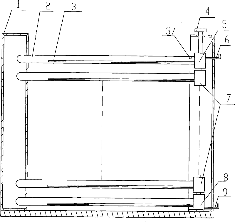
[0028] See attached figure 1 , the present invention uses the upper head 5, the middle head 7 and the lower head 8 to connect the vacuum tubes, so that the water system between the vacuum tubes forms a series connection, which greatly improves the effective conduction of the energy of the vacuum tube heat collector, and is suitable for For split solar water heaters. The vacuum tubes in the middle are connected through the middle head 7, which is a letter buckle connection, through the cooperation between the first head joint 14 on the middle head 7 and the first round hole 17, a water flow channel is formed, and The positioning protrusion 15 and the positioning circular hole 16 are positioned and coupled.

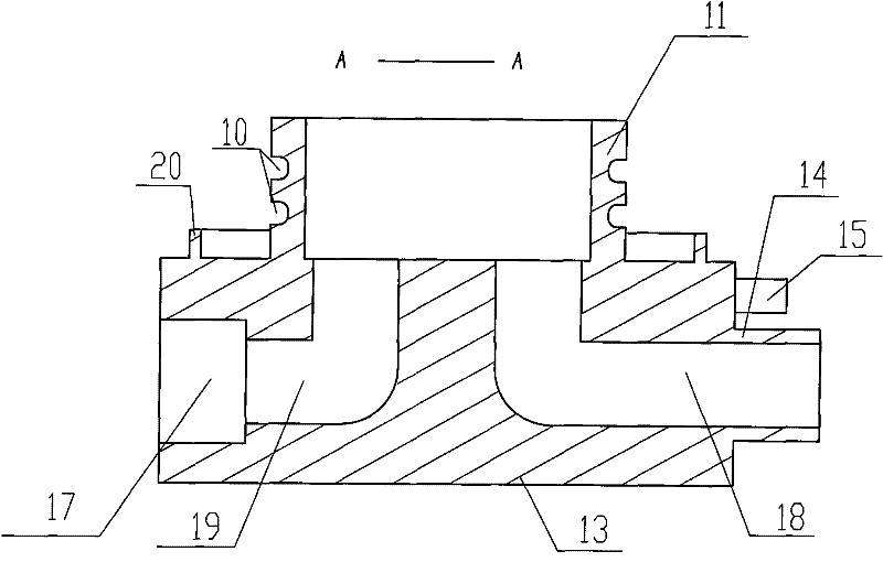
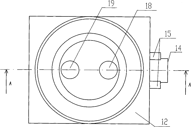
[0029] See attached figure 2 , attached image 3 , attached Figure 4 And attached Figure 5 , the description of the posi...


PUM


Abstract

The invention discloses an unpressurized serial solar energy vacuum tube heat collector. Vacuum tubes are connected in series by using an upper end enclosure, an intermediate end closure and a lower end enclosure; fixed frames are arranged at two ends of the vacuum tubes; a first water outlet channel which is communicated with the vacuum tubes and is set into 90 degrees is arranged at the right side of a first end enclosure main body along the axial direction of the first end enclosure main body of the intermediate end enclosure; a first water inlet channel which is communicated with the vacuum tubes and is set into 90 degrees is arranged at the left side of the first end enclosure main body; a first end enclosure joint is arranged at a water outlet of the first water outlet channel; a first circular hole is arranged at a water inlet of the first water inlet channel; a first vacuum tube joint is arranged at the upper part of the first end enclosure main body; and a first sealing groove is arranged on the circumferential wall of the first vacuum tube joint. The upper end enclosure and the lower enc enclosure are changed based on the structure of the intermediate end enclosure and are additionally provided with metal screw threads on the water outlet and the water inlet, so that the upper end enclosure and the lower end enclosure are convenient to communicate with an external water path system. The invention has the advantages of effective avoidance of water mixing during use, long service life and high heat efficiency.

Description

technical field [0001] The invention relates to a split-type solar heat collector, in particular to a non-pressure-bearing serial solar vacuum tube heat collector, which is suitable for household installation in high-rise buildings. Background technique [0002] The heat collector of the split type solar water heater used in the existing solar heat collection is divided into a large plate type and a vacuum tube type from the structure; from the operation mode to the pressure type and the non-pressure type. China's vacuum tube heat collection technology is at the leading level in the world, the installation mode is diversified, and the cost performance is higher than that of large flat panels. At present, vacuum tubes account for 90% of domestic heat collectors, and they are the first choice among solar heat collectors. When the pressure-bearing chemical medium is used to conduct heat collection, due to the serious limitation of energy loss in the transmission pipeline, the p...

Claims


Application Information

Patent Timeline
Patent Type & Authority Patents(China)
IPC IPC(8): F24J2/46F24J2/05F24S10/40
CPCY02E10/44
Inventor 王强
Owner 河北沃德沃姆新能源科技有限公司
Features
  • R&D
  • Intellectual Property
  • Life Sciences
  • Materials
  • Tech Scout
  • Unparalleled Data Quality
  • Higher Quality Content
  • 60% Fewer Hallucinations
Learn More