Manufacturing method of spiral bracket and spiral bracket

A helical and coating technology, which is applied in the manufacture of helical stents and the field of helical stents, can solve the problems of center deviation and coating layer center deviation, etc., and achieve the effects of prolonging life, high dielectric strength and high reliability

Inactive Publication Date: 2010-10-27
TOSHIN ELECTRIC
View PDF2 Cites 0 Cited by
  • Summary
  • Abstract
  • Description
  • Claims
  • Application Information

AI Technical Summary

Problems solved by technology

[0004] However, when using the above-mentioned conventional method, the center of the covering layer may be shifted when forming a long spiral insulated covered wire.
That is, the crosshead die of the extruder is set at a specific phase position of the long helical metal core wire discharged from the long spiral forming die, and the coating layer is formed at the specific phase position, although when the position of the crosshead die is relatively long helical When the position of the coating is not correct, the center of the coating layer will deviate, but the phase of the long helix and the mutual position of the crosshead die may also deviate due to other reasons such as vibration during the forming process of the coating wire, so the coating layer may be formed. The center deviates from the product, or the problem of partial center deviation

Method used


Image

  • Manufacturing method of spiral bracket and spiral bracket
  • Manufacturing method of spiral bracket and spiral bracket
  • Manufacturing method of spiral bracket and spiral bracket

Examples


Embodiment Construction

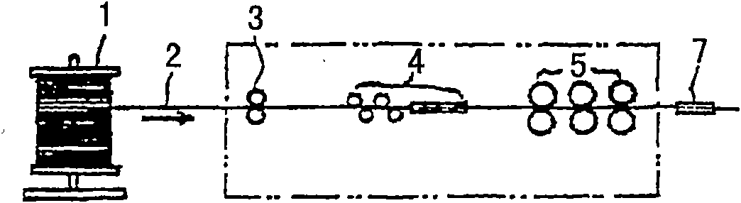
[0036] Embodiments of the present invention will be described below with reference to the drawings. figure 1 It is a schematic diagram of a device for feeding the tough metal core wire 2 wound on a spool forward (to the right in the drawing).

[0037] In this figure, reference numerals 5, 5... denote feed rollers, which are respectively arranged in a pair up and down, and are driven by a driving device not shown, and feed the metal wire 2 between grooves provided around the rollers. Here, reference numeral 3 is a guide roll, and reference numeral 4 is a straightening roll.

[0038] And, when the feed rollers 5, 5, ... are rotated, the metal core wire 2 can be fed forward, that is, toward the direction of the guide pipe 7.

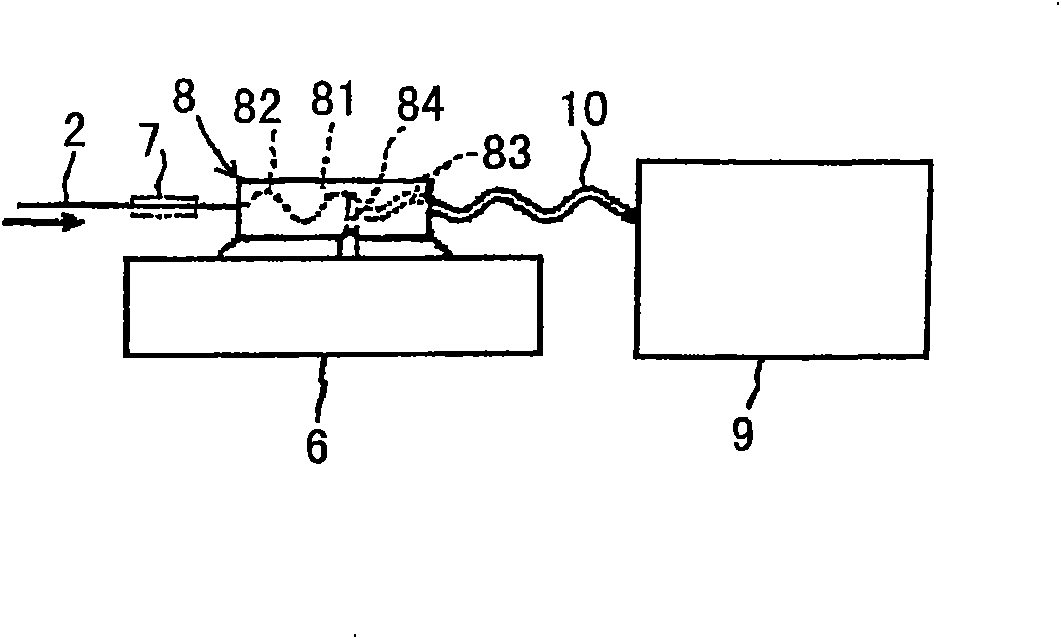
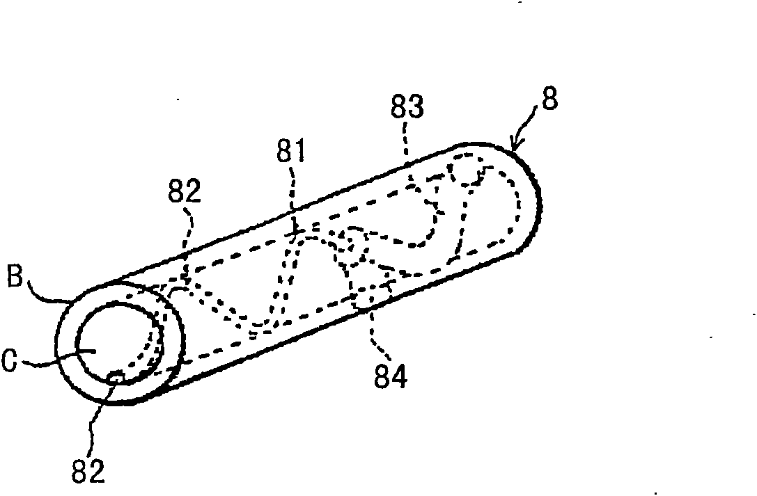
[0039] Next, the metal core wire 2 fed by the above process is introduced into the mold 8 provided with the long helical two-stage hole, and is forced to pass through the mold 8 to form the long helical metal wire, and the long helical wire is made of a po...


PUM


Abstract

The invention aims at providing a manufacturing method of a spiral bracket and the spiral bracket. The spiral bracket can prevent central deviation of a cover layer, and the correct position of a crosshead mould corresponding to the phase of a long screw can be set in a short time. The manufacturing method of the spiral bracket in the invention is as follows: a mould (8) in two section holes are fed by metal core wires (2), wherein the front part of the mould is a small hole (82) in long spiral forms through which metal wires can penetrate, the rear part is a big hole (83) with the inner diameter being greater than that of the above small hole (82). While the wire cores (2) are bent by the front part of the mould (8) into long spiral forms, the rear part of the mould (8) is coated by high polymer materials.

Description

[0001] This application is a divisional application, the filing date of the original application is August 1, 2005, the application number is 200510088686.5, and the title of the invention is the manufacturing method of the helical stent and the helical stent. technical field [0002] The present invention relates to a helical support for supporting insulated and covered electric wires and a manufacturing method thereof. Background technique [0003] In the conventional helical stent, first, the metal core wire is bent into a long helical shape by using a die provided with a long helical hole, and then the long helical metal core wire is introduced into a crosshead die of an extruder, and the entire surface of the metal core wire is Apply an insulating covering layer composed of a polymer material, and then cut the long spiral insulating covered wire into a predetermined length, and form a spiral stent with a predetermined shape such as a U shape in the middle part (refer to ...

Claims


Application Information

Patent Timeline
Patent Type & Authority Applications(China)
IPC IPC(8): H01B17/22
Inventor 塚本直明
Owner TOSHIN ELECTRIC
Why Eureka
Try Eureka