Electric connector

A technology of electrical connectors and contacts, which is applied in the direction of connection, two-part connection devices, parts of connection devices, etc. The effect of small contact resistance and increased contact area

Active Publication Date: 2012-04-11
BEIJING INSTITUTE OF TECHNOLOGYGY
View PDF0 Cites 0 Cited by
  • Summary
  • Abstract
  • Description
  • Claims
  • Application Information

AI Technical Summary

Problems solved by technology

However, because the electric connector with planar contact uses a coil spring, it has a large volume and low rigidity, and when the vehicle is running, the electric connector is easy to be falsely connected, causing failures such as ablation and poor contact.

Method used


Image

  • Electric connector
  • Electric connector
  • Electric connector

Examples


Embodiment Construction

[0026] In order to enable your examiners to further understand the structure, features and other purposes of the present invention, the attached preferred embodiments are now described in detail as follows. The described preferred embodiments are only used to illustrate the technical solutions of the present invention, not to limit the present invention. invention.

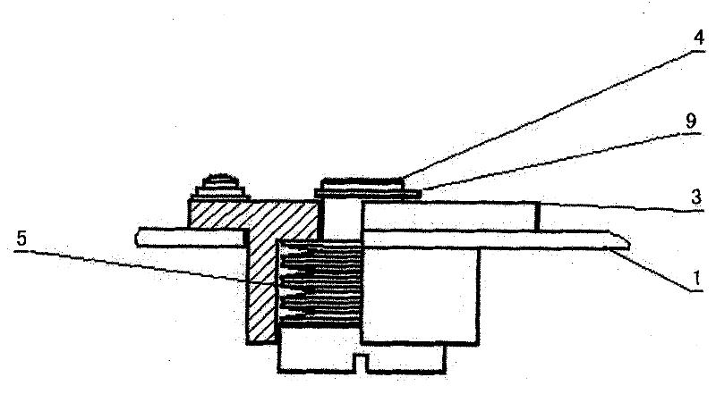
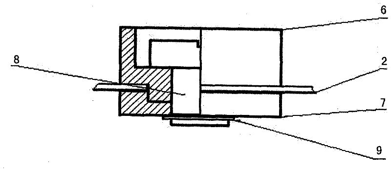
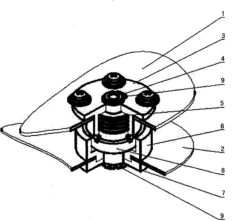
[0027] The electrical connector of the present invention comprises two contacts 4, 8, two insulating shells 3, 3' and disc springs 5, the longitudinal sections of these two contacts 4, 8 are "T" shaped, and are formed by The interconnected contact is formed by a fixed rod, and the contact is fixed at the end of the fixed rod. Wherein, the contact can be fixed on the end of the fixing rod by welding, or the contact and the fixing rod can be integrally processed. Such as Figure 4 as shown, Figure 4 It is a schematic structural diagram of the contacts of the invented electrical connector. Depend on Figure 4 I...


PUM


Abstract

The invention provides an electric connector which comprises two contact points, two insulating shells and a disk spring, wherein both the longitudinal sections of the two contact points are T-shaped, each contact point comprises a contact and a fixed rod which are mutually connected, the disk spring and one contact point are installed in one insulating shell, the disk spring is sleeved on the fixed rod of the contact point, the free end of the fixed rod of the contact point extends out of the insulating shell, and a snap ring is arranged at the free end, so that the free end only can move towards the direction far away from the insulating shell; the other contact point is fixed in the other insulating shell, the insulating shell comprises an outer insulating shell and an inner insulatingshell, perforated holes are arranged on the outer insulating shell and the inner insulating shell, the fixed rod of the contact point penetrates through the perforated holes, the free end of the fixed rod of the contact point extends out of the inner insulating shell, and a clamping firmware is arranged at the free end. The electric connector of the invention has the advantages of simple structure, low requirement for positioning precision and small occupied space.

Description

technical field [0001] The invention relates to an electrical connector, in particular to a high-rigidity elastic planar electrical connector, which belongs to the field of electrical technology. Background technique [0002] As a clean, environment-friendly and green vehicle, electric vehicles have attracted great attention from governments and automobile manufacturers around the world. Electric vehicles represented by pure electric vehicles, hybrid vehicles, and fuel cell vehicles will surely become important means of transportation in the 21st century. Among them, pure electric vehicles have experienced a long period of development, the technology is becoming more and more mature, and the relevant technical testing standard system has been perfected, and it has been commercialized and applied in the United States, Japan, Europe and other countries and regions, especially in special municipal applications. Vehicles, fixed-line buses, official fleet vehicles and private veh...

Claims


Application Information

Patent Timeline
Patent Type & Authority Patents(China)
IPC IPC(8): H01R24/00H01R13/02H01R13/24H01R13/502
Inventor 王震坡孙逢春
Owner BEIJING INSTITUTE OF TECHNOLOGYGY
Why Eureka
Try Eureka