Power supply device of universal charger

A technology for power supply devices and electrical appliances, which is applied to battery circuit devices, circuit devices, output power conversion devices, etc., and can solve the problems of large output voltage fluctuation range, low conversion efficiency, and high circuit cost

Inactive Publication Date: 2010-10-27
田剑彪
View PDF0 Cites 6 Cited by
  • Summary
  • Abstract
  • Description
  • Claims
  • Application Information

AI Technical Summary

Problems solved by technology

[0002] The power supply device of the universal charger currently used is composed of RCC circuit, as attached figure 1 As shown, the output voltage fluctuation range of this circuit is large, the conversion efficiency is low, the system reliability is poor, there are many peripheral components, and the circuit cost is high

Method used


Image

  • Power supply device of universal charger
  • Power supply device of universal charger
  • Power supply device of universal charger

Examples


Embodiment Construction

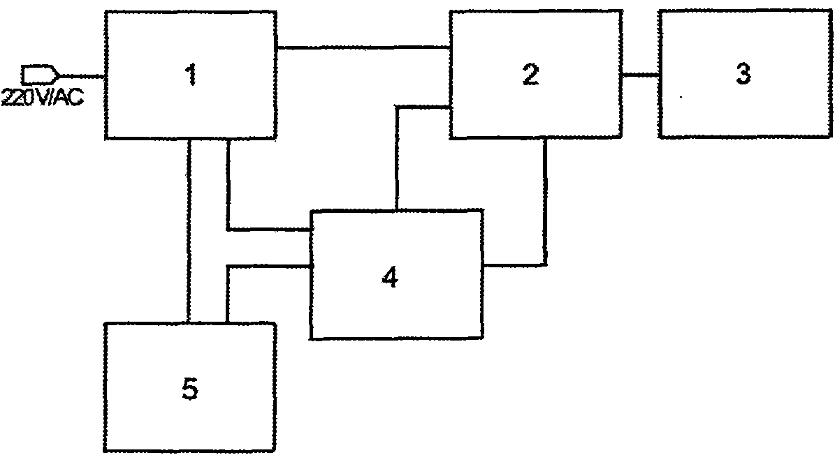
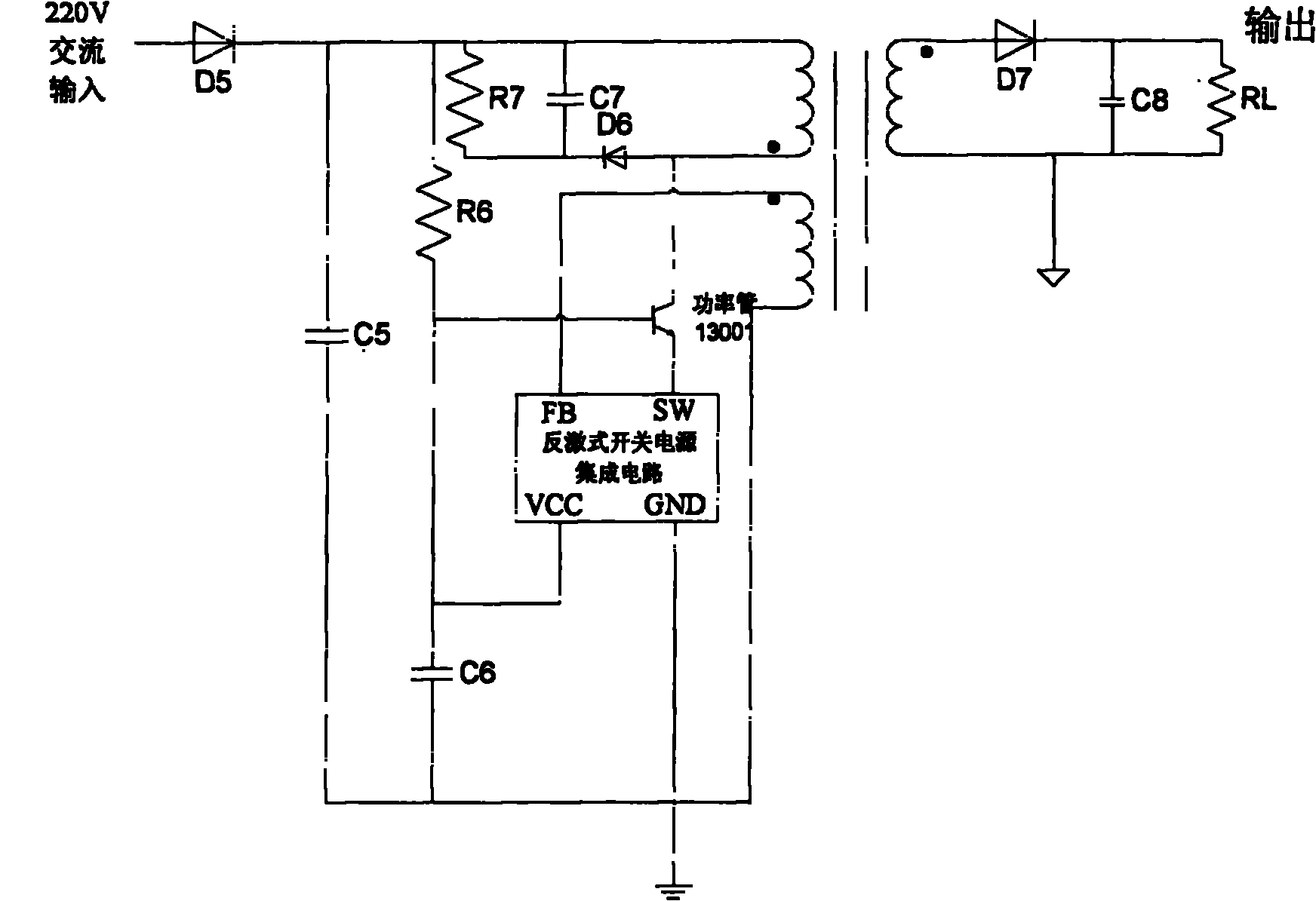
[0019] exist figure 2 with image 3 Middle: the present invention includes a rectification and filtering circuit 1, a converter 2 and an output circuit 3 connected in sequence, the rectification and filtering circuit 1 is connected with a start-up circuit 5, and the rectification and filter circuit 1, the converter 2 and a start-up circuit 5 are respectively connected to the flyback The switching power supply integrated circuit 4 is connected, and the rectification and filtering circuit 1 is composed of a diode D5 and a capacitor C5; R6 and capacitor C6 are connected in series, the FB pin of the flyback switching power supply integrated circuit 4 is connected to the secondary coil in the converter 2, the SW pin is connected to the emitter of the power tube 13001, and the collector of the power tube 13001 is connected to the main The coils are connected, the VCC pin is connected to the positive pole of the capacitor C6, and the GND pin is grounded.

[0020] The 85V~220V AC i...


PUM


Abstract

The invention aims to provide a power supply device of a universal charger, which has the advantages of reasonable structure design, stable performance and low cost. The power supply device comprises a rectifying and filtering circuit, a converter and an output circuit which are sequentially connected, wherein, the rectifying and filtering circuit is connected with a starting circuit. The power supply device is characterized in that the rectifying and filtering circuit, the converter and the starting circuit are respectively connected with a flyback switching power supply integrated circuit. As the flyback switching power supply integrated circuit is adopted, output signals are stable, and the reliability and the working efficiency are improved. The power supply device of the invention is one of the ideal power supply devices of the universal charger at present.

Description

technical field [0001] The invention belongs to the technical field of charger circuits, in particular to a power supply device for a universal charger. Background technique [0002] The power supply device of the universal charger currently used is composed of RCC circuit, as attached figure 1 As shown, the output voltage fluctuation range of this circuit is large, the conversion efficiency is low, the system reliability is poor, there are many peripheral components, and the circuit cost is high. Principle analysis: Diode IN4007 and high-voltage capacitor C1 form an AC rectification filter circuit, R1 is a starting resistor, and after Q1 is turned on, a positive feedback loop formed by R3, C2 and the transformer feedback winding generates self-excited oscillation, and ZD1, D2, and C3 are composed of The voltage stabilization loop stabilizes the induced voltage of the feedback winding within the set value, and then keeps the voltage of the output winding constant; R5 is the...

Claims


Application Information

Patent Timeline
Patent Type & Authority Applications(China)
IPC IPC(8): H02J7/00H02M3/00H02M3/135
Inventor 田剑彪
Owner 田剑彪
Why Eureka
Try Eureka