Chemical reactor with plate type heat exchange unit

A heat exchange unit and chemical reactor technology, applied in the field of chemical reactors, can solve the problems of impossibility cannot exceed a certain limit, cannot reduce welding points, and is not easy to apply, etc., and achieves high mechanical strength and large exchange surface. , the effect of easy installation

A heat exchange unit and chemical reactor technology, applied in the field of chemical reactors, can solve the problems of impossibility cannot exceed a certain limit, cannot reduce welding points, and is not easy to apply, etc., and achieves high mechanical strength and large exchange surface. , the effect of easy installation

CN101873889AInactive Publication Date: 2010-10-27METHANOL CASALE SA

Image

  • Chemical reactor with plate type heat exchange unit
  • Chemical reactor with plate type heat exchange unit
  • Chemical reactor with plate type heat exchange unit

Examples


Embodiment Construction

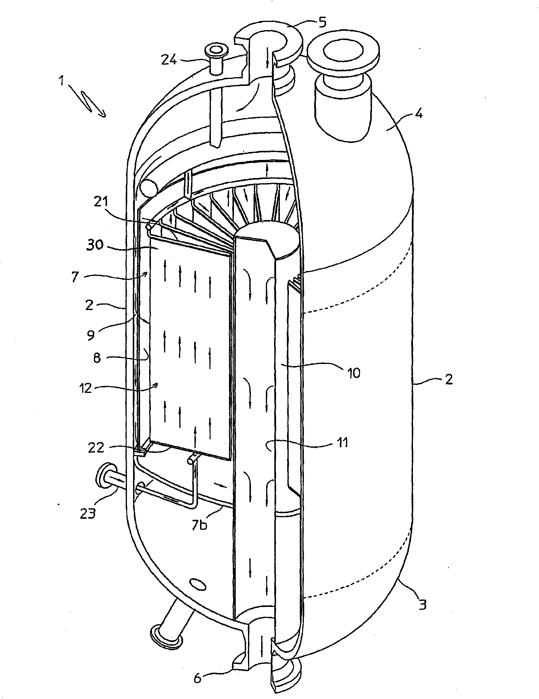
[0039] refer to figure 1 , the shown isothermal chemical reactor 1 comprises a cylindrical housing 2 with a vertical axis, a lower end 3 and an upper end 4 equipped with flanges 5 for the inlet of the reagents and 6 for the outlet of the reaction products, respectively.

[0040] figure 1 An example of is a catalytic reactor, for example, for the synthesis of methanol, which comprises a catalytic rack 7 which is substantially cylindrical and ring-shaped. The catalytic shelf 7 is mainly composed of an outer cylindrical wall 8, an inner cylindrical wall 10 and an annular bottom 7b. The outer wall 8 with the cover 2 defines a gap 9 of reduced width. Rack 7 is intended to contain a number of suitable catalysts (not shown).

[0041] Said outer wall 8 and said inner wall 10 are perforated so as to allow the passage of reagent gases from the gap 9 into the shelf 7 and of the gaseous reaction products from the shelf 7 to the central duct 11 which constitutes said reaction products ...


PUM


Abstract

An isothermal chemical reactor (1) is described comprising a plate (30) heat exchange unit (12), immersed in a catalytic bed (7) and destined to heat or cool the reagents in order to maintain the reaction temperature in a predetermined range; said plates (30) are formed by two flat walls (31, 32) and longitudinal spacers (33), with obtainment of parallel channels (34) for the circulation of a heat exchange fluid.

Description

technical field [0001] In its most general aspect, the invention relates to the technical field of chemical reactors internally equipped with plate heat exchange units or plate heat exchangers. [0002] As a non-limiting example, the invention is applicable to isothermal or pseudo-isothermal chemical reactors (for exothermic or endothermic heterogeneous reactions) equipped with internal heat exchangers immersed in catalytic layers, or equipped with operating conditions Reactor with internal heat exchanger submerged in fluid. Background technique [0003] Different types of known chemical reactors are equipped with at least one internal heat exchanger suitable for supplying or removing heat from the chemical reactions taking place within the reactor itself. [0004] The first example describes a so-called isothermal or pseudo-isothermal reactor, usually comprising a heat exchanger immersed in a catalytic layer, the purpose of which is to remove heat from the reagents in the ...

Claims


Application Information

Patent Timeline
27 Oct 2010
Publication
CN101873889A
IPC
B01J8/02; B01J19/00; F28D9/00
CPC
B01J19/0013; B01J8/0285; F28D9/0006; F28D9/0062; B01J8/0214; F28F2240/00; B01J2219/00085; B01J2208/0015
Inventors
恩里科·力兹; 埃曼诺·菲利浦