Fuel cell system and method of operating the same

A fuel cell system, fuel cell technology, applied in the direction of fuel cells, fuel cell additives, fuel cell heat exchange, etc.

Inactive Publication Date: 2010-10-27
PANASONIC CORP
View PDF5 Cites 9 Cited by
  • Summary
  • Abstract
  • Description
  • Claims
  • Application Information

AI Technical Summary

Problems solved by technology

[0004] However, even if the anode catalyst is made of such a material resistant to CO poisoning, in order to ensure its catalytic activity, the CO concentration in the fuel gas has to be kept below 10ppm.

Method used


Image

  • Fuel cell system and method of operating the same
  • Fuel cell system and method of operating the same
  • Fuel cell system and method of operating the same

Examples


Embodiment approach 1

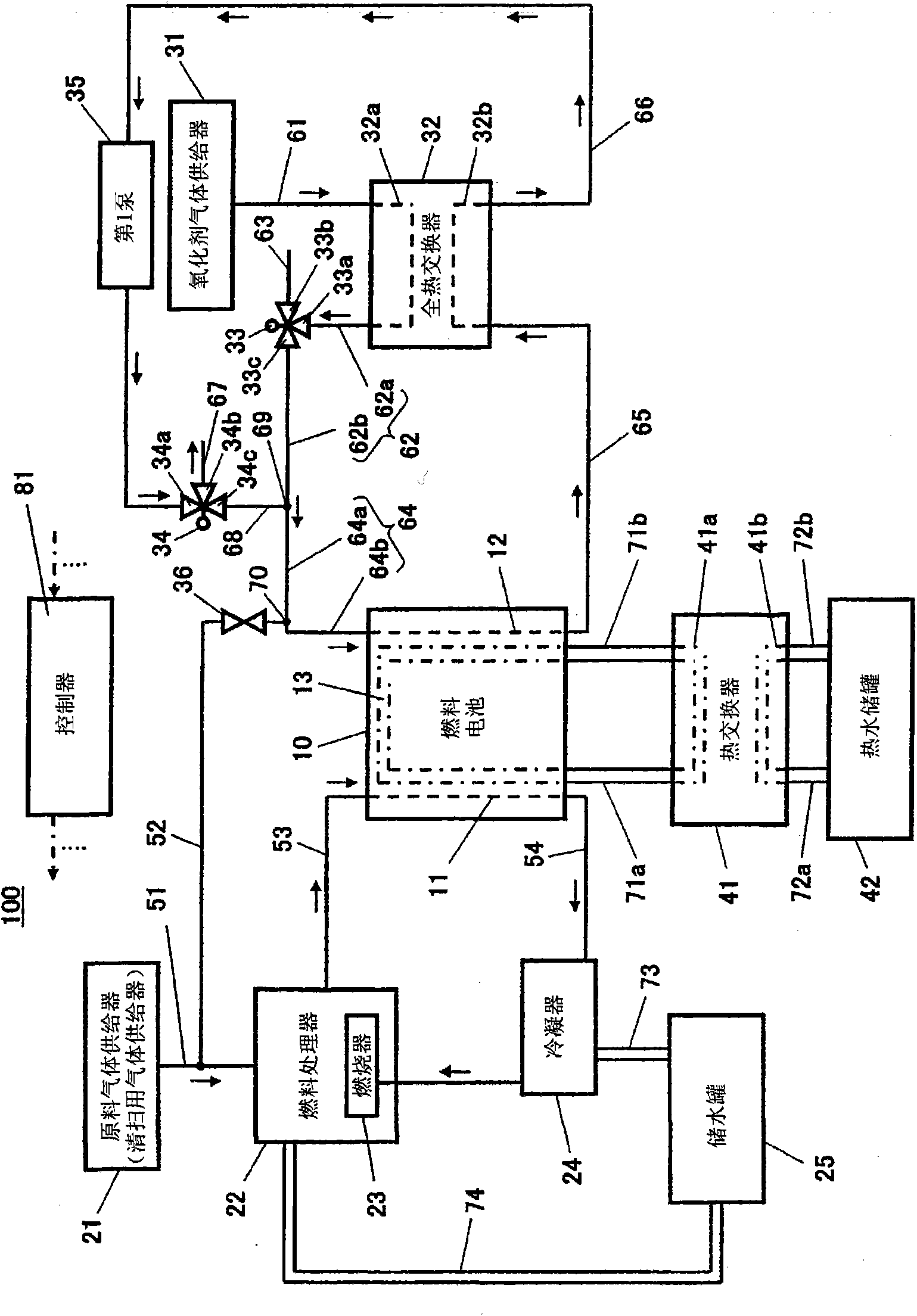
[0139] figure 1 It is a schematic diagram showing a schematic configuration of the fuel cell system according to Embodiment 1 of the present invention, and schematically shows the flow of reactant gas during power generation by the fuel cell.

[0140] [Configuration of fuel cell system]

[0141] Such as figure 1 As shown, the fuel cell system 100 according to Embodiment 1 includes the fuel cell 10 , a fuel gas supply system, an oxidant gas supply system, a cooling system, and a controller 81 . The fuel gas supply system is configured to supply fuel gas to the fuel cell 10 and includes a raw material gas supplier (scavenging gas supplier) 21 , a fuel processor (fuel gas supplier) 22 , and a condenser 24 . In addition, the oxidant gas supply system is configured to supply oxidant gas to the fuel cell 10 , and has an oxidant gas supplier 31 and a total heat exchanger (moisture exchanger) 32 .

[0142] First, the configuration of the fuel cell 10 will be described below.

[01...

Embodiment approach 2

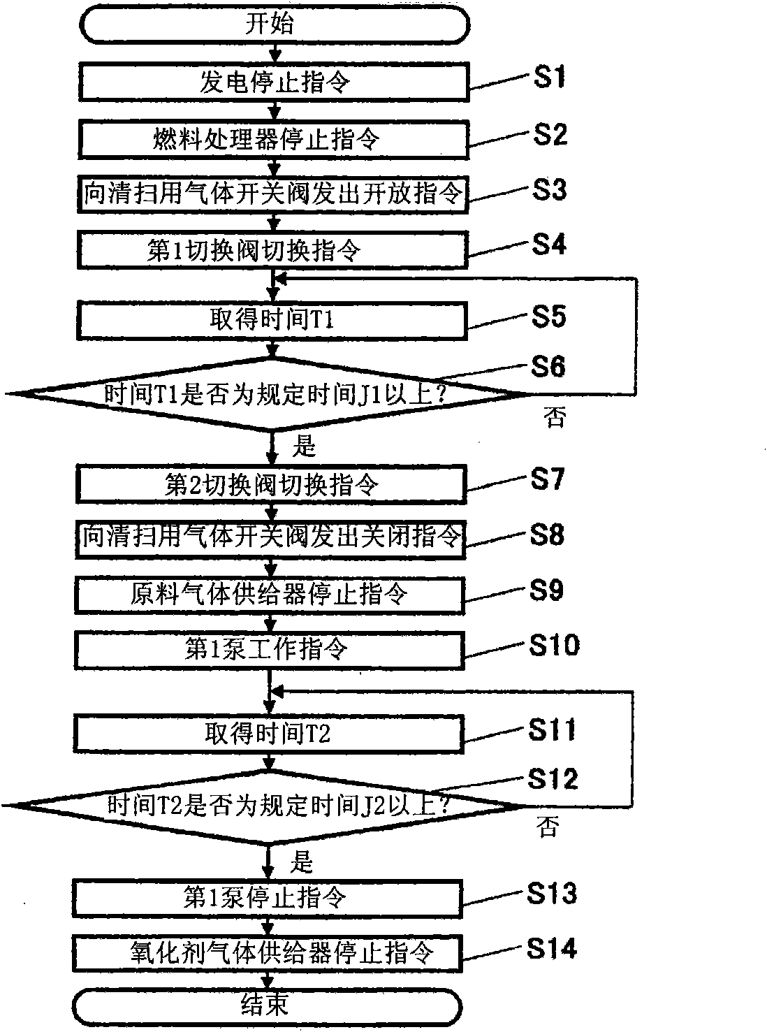
[0188] Figure 6 It is a schematic diagram showing a schematic configuration of a fuel cell system according to Embodiment 2 of the present invention, and schematically shows the flow of reactant gas during fuel cell power generation operation. Figure 7 It is a flowchart schematically showing the contents of the operation stop operation program stored in the storage unit of the controller in the fuel cell system according to the second embodiment.

[0189] Such as Figure 6 As shown, the basic configuration of the fuel cell system 100 according to Embodiment 2 is the same as that of the fuel cell system 100 according to Embodiment 1, but differs in that a voltage detector 82 is provided. Specifically, the voltage detector 82 is connected between a pair of electrical output terminals (not shown) of the fuel cell 10 . Also, the voltage detector 82 communicates the detected voltage value to the controller 81 . In addition, as the voltage detector 82, a well-known voltage dete...

Embodiment approach 3

[0194] Figure 8 It is a schematic diagram showing a schematic configuration of a fuel cell system according to Embodiment 3 of the present invention, and schematically shows the flow of reactant gas when the fuel cell generates electricity. Figure 9 It is a flowchart schematically showing the contents of the operation stop operation program stored in the storage unit of the controller in the fuel cell system according to the third embodiment.

[0195] Such as Figure 8 As shown, the basic configuration of the fuel cell system 100 according to Embodiment 3 is the same as that of the fuel cell system 100 according to Embodiment 1, but differs in that a temperature detector 84 is provided. Specifically, the temperature detector 84 is arranged in the middle of the first heat medium outgoing path 71a so as to be able to detect the temperature of the fuel cell 10, and is configured to detect the temperature of the first heat medium discharged from the fuel cell 10 as a fuel The ...


PUM


Abstract

A fuel cell system includes a fuel cell (10) having an inner fuel gas path (11) and an inner oxidant gas path (12), oxidant gas supply paths (62, 64), an oxidant gas supplier (31), oxidant gas discharge paths (65, 66) having upstream ends connected to the inner oxidant gas path (12) and downstream ends connected to the oxidant gas supply path (64), a water content exchanger (32) mounted so as to straddle the oxidant gas supply path (62) and the oxidant gas discharge path (65), a gas circulation path former / eliminator (34) provided in the oxidant gas discharge path (66), a fan (35) for circulating gas in a gas circulation path, and an atmosphere connector / interrupter (33) provided in the oxidant gas supply path (62).

Description

technical field [0001] The present invention relates to a fuel cell system and an operating method thereof, and particularly to a fuel cell system and an operating method thereof in which it is desired to prevent a reduction in the CO poisoning resistance of a catalyst on the anode. Background technique [0002] A fuel cell system generally has a structure in which a plurality of cells are stacked. Each cell includes: an electrolyte layer for transporting ions; The fuel gas channel flowing while contacting the anode is formed as an oxidizing gas channel through which the oxidizing gas flows while contacting the cathode. Hydrogen, which is the fuel gas used in such a fuel cell system, does not have an infrastructure supply facility, so a fuel processor is generally installed in parallel with a fuel cell for home use. The fuel processor generally has a reformer for reforming city gas equipped with an infrastructure supply facility into hydrogen-rich reformed gas. However, th...

Claims


Application Information

Patent Timeline
Patent Type & Authority Applications(China)
IPC IPC(8): H01M8/04H01M8/06H01M8/10
CPCH01M8/04097H01M8/04835H01M8/04119H01M8/04141H01M8/04992H01M8/04335Y02E60/50H01M8/04753H01M2008/1095H01M8/04328H01M8/04395H01M8/04007
Inventor 酒井修安本荣一菅原靖小原英夫浦田隆行
Owner PANASONIC CORP
Why Eureka
Try Eureka