Pumping unit system and power saving control method thereof

A technology of pumping unit and sucker rod, which is applied in the control system, automatic control system of drilling, mechanical equipment, etc., to achieve the effect of reducing power, reducing negative work and high efficiency

Inactive Publication Date: 2014-01-15
杭州坤泽采油设备有限公司
View PDF9 Cites 0 Cited by
  • Summary
  • Abstract
  • Description
  • Claims
  • Application Information

AI Technical Summary

Problems solved by technology

[0007] The technical problem to be solved by the present invention is to provide a pumping unit system for the deficiencies of the prior art, which solves the problem of the motor doing negative work during operation, thereby reducing energy consumption and improving overall efficiency and overload capacity

Method used


Image

  • Pumping unit system and power saving control method thereof
  • Pumping unit system and power saving control method thereof
  • Pumping unit system and power saving control method thereof

Examples


Embodiment Construction

[0029] Embodiments of the present invention will be specifically described below with reference to the accompanying drawings.

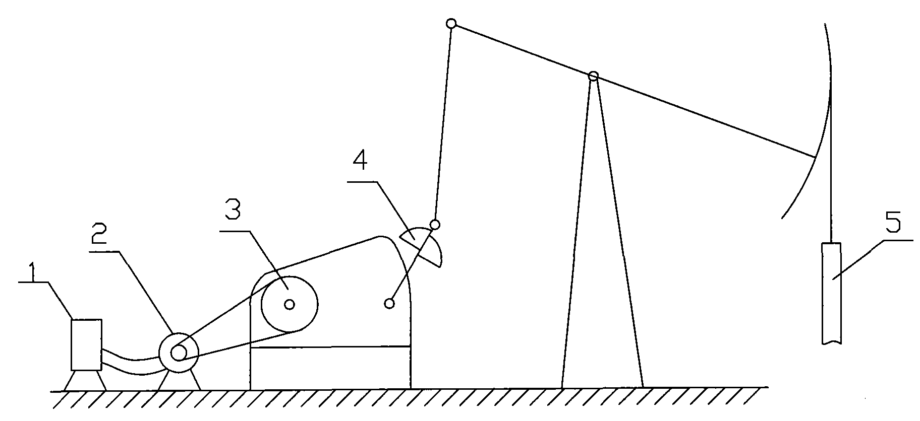
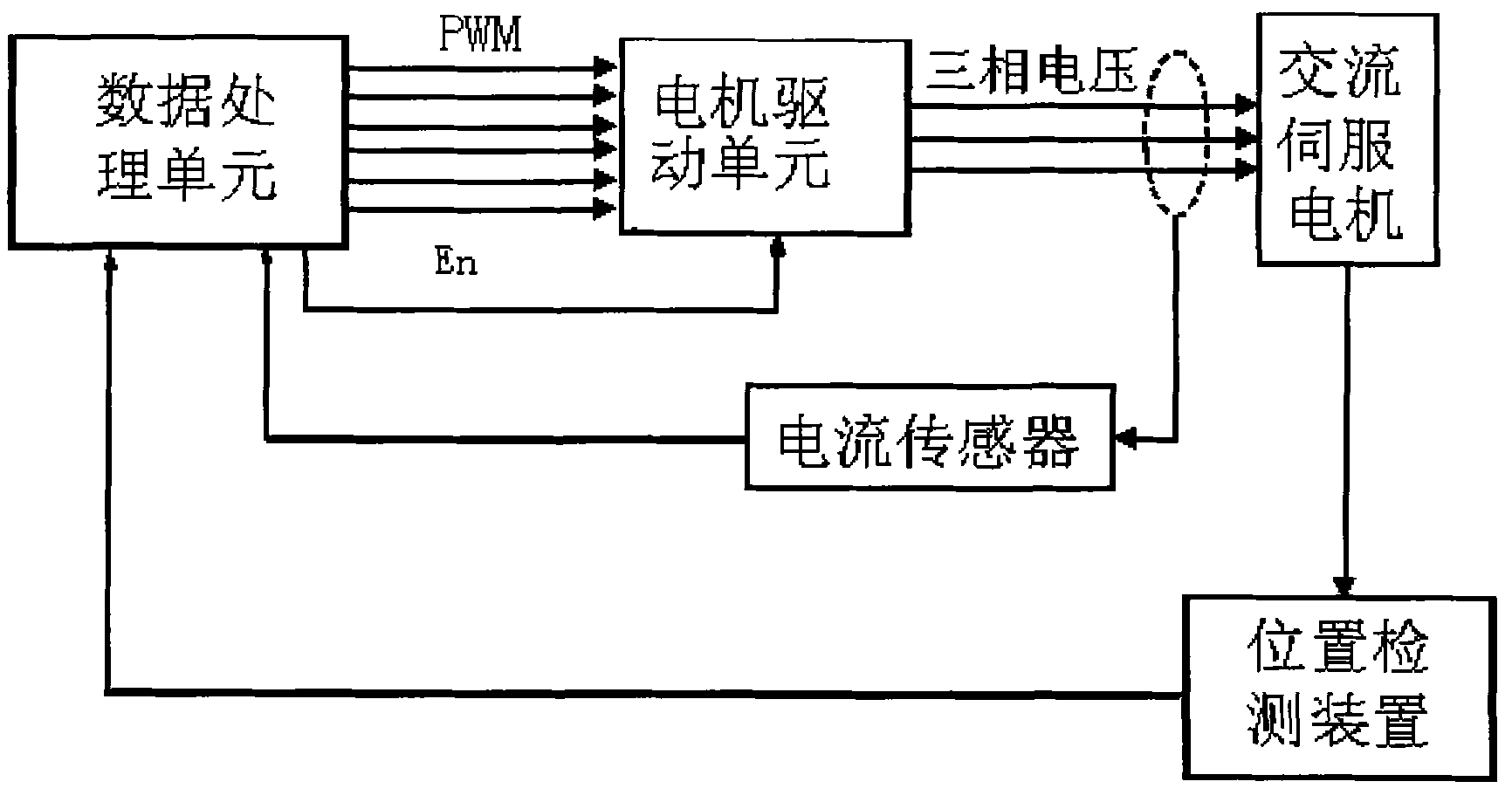
[0030] figure 1 is the schematic diagram of the pumping unit system, figure 2 It is a schematic diagram of the motor drive system control. Such as figure 1 As shown, the pumping unit system includes a drag motor 2, a transmission part 3, a counterweight 4 (and a sucker rod 5, and the drag motor 1 drives the sucker rod 5 to reciprocate up and down through the transmission part 2. The sucker rod 5 is controlled by a Weight 4 to balance.The pumping unit system also includes a control module 1, which can be implemented in the form of a control box during specific implementation, such as figure 1 shown. The shaft of the drag motor is provided with a position detection module, and the power input side of the motor is provided with a current sensor. The control module 1 receives the information representing the position of the drag motor output by the p...


PUM


Abstract

A pumping unit system and electricity-saving control method thereof are disclosed. The system includes a control module (1), a driving motor (2), a transmission part (3), a counterweight (4) and a sucker rod (5). The driving motor drives the sucker rod to reciprocate up and down by the transmission part; a position detection module is provided on the shaft of the driving motor, and a current sensor is provided on the input side of the power source of the motor; the control module receives a position information of the driving motor which is outputted from the position detection module and a current information of the driving motor which is outputted from the current sensor, thus realizing a closed-loop control of the driving motor and a judgement of state of doing work during operation of the motor, and turning off the motor when doing negative work. The electricity-saving control method includes the following steps: detecting the state of doing work of the driving motor when the pumping unit is running, judging whether the motor does negative work or not, cutting off power supply to the driving motor if the work is negative. Thus the invention has the merits of electricity-saving, stepless speed regulation, soft start and strong overload capacity.

Description

technical field [0001] The invention relates to an oil pumping system applicable to an oil field, in particular to an oil pumping unit system. Background technique [0002] The pumping unit, especially the beam pumping unit, is one of the most widely used oil mining machinery, and it is also a large power consumer in the oil field. Its power consumption accounts for about 40% of the total power consumption of the oil field, and its overall efficiency is very low. [0003] The beam pumping unit includes a motor drive system, a four-bar linkage mechanism and a donkey head. When the beam pumping unit is working, the motor drives the reducer through a belt drive, and drives the four-bar linkage mechanism to realize the donkey head swinging up and down. The head drives the sucker rod to make the downhole piston pump reciprocate up and down to complete the oil pumping work. [0004] When the pumping unit in the oil field is working, the load changes greatly and changes periodical...

Claims


Application Information

Patent Timeline
Patent Type & Authority Patents(China)
IPC IPC(8): E21B43/00E21B44/00
CPCH02P6/002H02P6/20E21B43/127F04B47/02H02P6/28E21B47/009
Inventor 郝双晖郝明晖
Owner 杭州坤泽采油设备有限公司
Why Eureka
Try Eureka